Nissan Maxima. Manual - part 468


  Index      Nissan     Nissan Maxima (2009-2014 year) - Service and Repair Manual


Search            


Content   ..  466  467  468  469   ..


Nissan Maxima. Manual - part 468


EC-356

< DTC/CIRCUIT DIAGNOSIS >

[VQ35DE]

P0453 EVAP CONTROL SYSTEM PRESSURE SENSOR

YES

>> GO TO 17.

NO

>> Replace EVAP control system pressure sensor. Refer to 

FL-17, "Removal and Installation"

.

17.

CHECK DRAIN FILTER

Refer to 

EC-356, "Component Inspection"

.

Is the inspection result normal?

YES

>> GO TO 18.

NO

>> Replace drain filter.

18.

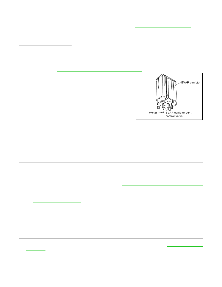
CHECK IF EVAP CANISTER IS SATURATED WITH WATER

1. Remove EVAP canister with EVAP canister vent control valve and EVAP control system pressure sensor

attached. Refer to 

FL-14, "Removal and Installation (EVAP Canister)"

.

2. Check if water will drain from the EVAP canister.
Does water drain from the EVAP canister?

YES

>> GO TO 19.

NO

>> GO TO 21.

19.

CHECK EVAP CANISTER

Weigh the EVAP canister with the EVAP canister vent control valve and EVAP control system pressure sensor

attached.

The weight should be less than 2.1 kg (4.6 lb).
Is the inspection result normal?

YES

>> GO TO 21.

NO

>> GO TO 20.

20.

DETECT MALFUNCTIONING PART

Check the following.

• EVAP canister for damage

• EVAP hose between EVAP canister and drain filter for clogging or poor connection

>> Repair hose or replace EVAP canister. Refer to 

FL-14, "Removal and Installation (EVAP Canis-

ter)"

.

21.

CHECK INTERMITTENT INCIDENT

Refer to 

GI-41, "Intermittent Incident"

.

>> INSPECTION END

Component Inspection

INFOID:0000000010095035

EVAP CONTROL SYSTEM PRESSURE SENSOR

1.

CHECK EVAP CONTROL SYSTEM PRESSURE SENSOR

1. Turn ignition switch OFF.

2. Remove EVAP control system pressure sensor with its harness connector. Refer to 

FL-17, "Removal and

Installation"

.

Always replace O-ring with a new one.

3. Install a vacuum pump to EVAP control system pressure sensor.

PBIB1213E

P0453 EVAP CONTROL SYSTEM PRESSURE SENSOR

EC-357

< DTC/CIRCUIT DIAGNOSIS >

[VQ35DE]

C

D

E

F

G

H

I

J

K

L

M

A

EC

N

P

O

4. Turn ignition switch ON and check output voltage between ECM

terminals under the following conditions.

CAUTION:

• Always calibrate the vacuum pump gauge when using it.
• Never apply below -93.3 kPa (-0.952 kg/cm

2

, -13.53 psi) or pressure over 101.3 kPa (1.033 kg/cm

2

,

14.69 psi).

Is the inspection result normal?

YES

>> INSPECTION END

NO

>> Replace EVAP control system pressure sensor. Refer to 

FL-17, "Removal and Installation"

.

DRAIN FILTER

1. Check visually for insect nests in the drain filter air inlet.
2. Check visually for cracks or flaws in the appearance.
3. Check visually for cracks or flaws in the hose.
4. Blow air into port A and check that it flows freely out of port B.
5. Block port B.
6. Blow air into port A and check that there is no leakage.
7. If NG, replace drain filter.

ECM

Applied vacu-

um kPa

(kg/cm

2

, psi)

Voltage

Con-

nector

+

Terminal

Terminal

E10

86

(EVAP control 

system pressure 

sensor signal)

96

(Sensor 
ground)

Not applied

1.8 - 4.8 V

-26.7 (-0.272, 

-3.87)

2.1 to 2.5 V lower 
than above value

JMBIA1871ZZ

PBIB3641E

EC-358

< DTC/CIRCUIT DIAGNOSIS >

[VQ35DE]

P0455 EVAP CONTROL SYSTEM

P0455 EVAP CONTROL SYSTEM

DTC Logic

INFOID:0000000010095036

DTC DETECTION LOGIC

This diagnosis detects a very large leakage (fuel filler cap fell off etc.) in EVAP system between the fuel tank

and EVAP canister purge volume control solenoid valve.

CAUTION:

• Use only a genuine NISSAN fuel filler cap as a replacement. If an incorrect fuel filler cap is used, the

MIL may illuminate.

• If the fuel filler cap is not tightened properly, the MIL may illuminate.

• Use only a genuine NISSAN rubber tube as a replacement.

DTC CONFIRMATION PROCEDURE

1.

PRECONDITIONING

DTC No.

Trouble diagnosis name

DTC detecting condition

Possible cause

P0455

EVAP control system 
gross leakage detected

EVAP control system has a very large leakage 
such as fuel filler cap fell off, EVAP control sys-
tem does not operate properly.

• Fuel filler cap remains open or fails to 

close.

• Incorrect fuel tank vacuum relief valve
• Incorrect fuel filler cap used
• Foreign matter caught in fuel filler cap.
• Leakage is in line between intake mani-

fold and EVAP canister purge volume 
control solenoid valve.

• Foreign matter caught in EVAP canister 

vent control valve.

• EVAP canister or fuel tank leakage
• EVAP purge line (pipe and rubber tube) 

leakage

• EVAP purge line rubber tube bent.
• Loose or disconnected rubber tube
• EVAP canister vent control valve and the 

circuit

• Drain filter
• EVAP canister purge volume control so-

lenoid valve and the circuit

• Fuel tank temperature sensor
• O-ring of EVAP canister vent control 

valve is missing or damaged.

• EVAP control system pressure sensor
• Refueling EVAP vapor cut valve
• ORVR system leakage

PBIB3640E

P0455 EVAP CONTROL SYSTEM

EC-359

< DTC/CIRCUIT DIAGNOSIS >

[VQ35DE]

C

D

E

F

G

H

I

J

K

L

M

A

EC

N

P

O

CAUTION:

Never remove fuel filler cap during the DTC Confirmation Procedure.

If DTC Confirmation Procedure has been previously conducted, always perform the following before conduct-

ing the next test.

1. Turn ignition switch OFF and wait at least 10 seconds.

2. Turn ignition switch ON.

3. Turn ignition switch OFF and wait at least 10 seconds.

Check that EVAP hoses are connected to EVAP canister purge volume control solenoid valve properly.

TESTING CONDITION:

• Perform “DTC WORK SUPPORT” when the fuel level is between 1/4 and 3/4 full, and vehicle is placed

on flat level surface.

• Open engine hood before conducting the following procedures.
Will CONSULT be used?

YES

>> GO TO 2.

NO

>> GO TO 4.

2.

PERFORM DTC CONFIRMATION PROCEDURE

With CONSULT

1. Tighten fuel filler cap securely until ratcheting sound is heard.

2. Turn ignition switch ON.

3. Turn ignition switch OFF and wait at least 10 seconds.

4. Turn ignition switch ON and select “DATA MONITOR” mode with CONSULT.

5. Check that the following conditions are met.

COOLAN TEMP/S: 0 - 70

°C (32 - 158°F)

INT/A TEMP SE: 0 - 60

°C (32 - 140°F)

6. Select “EVP V/S LEAK P0456/P1456” of “EVAPORATIVE SYSTEM” in “DTC WORK SUPPORT” mode

with CONSULT.

Follow the instructions displayed.

NOTE:

If the engine speed cannot be maintained within the range displayed on the CONSULT screen, go to 

EC-

14, "BASIC INSPECTION : Special Repair Requirement"

.

Which is displayed on CONSULT screen?

OK

>> INSPECTION END

NG

>> GO TO 3.

3.

CHECK DTC

Check DTC.
Which DTC is detected?

P0455 >> Go to 

EC-360, "Diagnosis Procedure"

.

P0442 >> Go to 

EC-317, "Diagnosis Procedure"

.

4.

PERFORM DTC CONFIRMATION PROCEDURE

With GST

NOTE:

Be sure to read the explanation of 

EC-26, "SRT Set Driving Pattern"

 before driving vehicle.

1. Start engine.

2. Drive vehicle according to 

EC-26, "SRT Set Driving Pattern"

.

3. Stop vehicle.

4. Turn ignition switch OFF and wait at least 10 seconds.

5. Turn ignition switch ON.

6. Turn ignition switch OFF and wait at least 10 seconds.

7. Turn ignition switch ON.

8. Check 1st trip DTC.
Is 1st trip DTC detected?

YES-1 >> P0455: Refer to 

EC-360, "Diagnosis Procedure"

.

YES-2 >> P0442: Refer to 

EC-317, "Diagnosis Procedure"

.

YES-3 >> P0441: Refer to 

EC-312, "Diagnosis Procedure"

.

NO

>> INSPECTION END


Content   ..  466  467  468  469   ..