Nissan Maxima. Manual - part 466
EC-348
< DTC/CIRCUIT DIAGNOSIS >
[VQ35DE]
P0452 EVAP CONTROL SYSTEM PRESSURE SENSOR
1. Start engine and warm it up to normal operating temperature.
2. Set voltmeter probes to ECM harness connector terminals under the following conditions.
3. Check that the voltage is less than 4.2 V.
4. Turn ignition switch OFF and wait at least 10 seconds.
5. Turn ignition switch ON.
6. Turn ignition switch OFF and wait at least 10 seconds.
7. Start engine and wait at least 20 seconds.
8. Check 1st trip DTC.
Is 1st trip DTC detected?
YES
>> Go to
NO
>> INSPECTION END
Diagnosis Procedure
INFOID:0000000010095030
Regarding Wiring Diagram information, refer to
.
1.
CHECK GROUND CONNECTION
1. Turn ignition switch OFF.
2. Check ground connection E9. Refer to Ground Inspection in
.
Is the inspection result normal?
YES
>> GO TO 2.
NO
>> Repair or replace ground connection.
2.
CHECK CONNECTOR
1. Disconnect EVAP control system pressure sensor harness connector.
2. Check that water is not inside connectors.
Is the inspection result normal?
YES
>> GO TO 3.
NO
>> Repair or replace harness connector.
3.
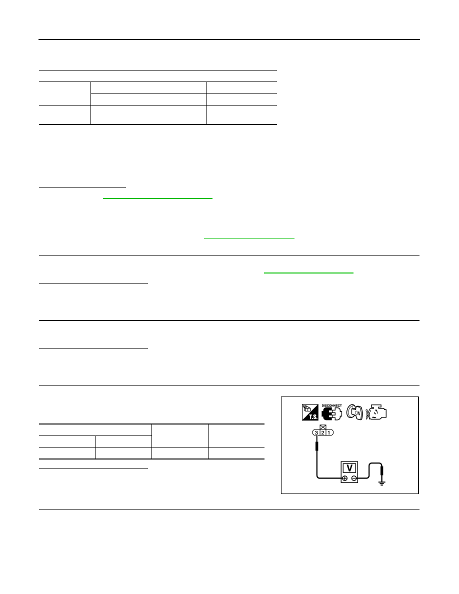
CHECK EVAP CONTROL SYSTEM PRESSURE SENSOR POWER SUPPLY CIRCUIT-I
1. Turn ignition switch ON.
2. Check the voltage between EVAP control system pressure sen-
sor harness connector and ground.
Is the inspection result normal?
YES
>> GO TO 10.
NO
>> GO TO 4.
4.
CHECK EVAP CONTROL SYSTEM PRESSURE SENSOR POWER SUPPLY CIRCUIT-II
1. Turn ignition switch OFF.
2. Disconnect ECM harness connector.
3. Check the continuity between EVAP control system pressure sensor harness connector and ECM har-
ness connector.
ECM
Connector
+
–
Terminal
Terminal
E10
95
(Fuel tank temperature sensor signal)
104
(Sensor ground)
EVAP control system pressure sensor
Ground
Voltage (V)
Connector
Terminal
B41
3
Ground
Approx. 5
PBIB0138E