Nissan Maxima. Manual - part 464
EC-340
< DTC/CIRCUIT DIAGNOSIS >
[VQ35DE]
P0448 EVAP CANISTER VENT CONTROL VALVE
YES
>> GO TO 7.
NO
>> GO TO 6.
6.
DETECT MALFUNCTIONING PART
Check the following.
• EVAP canister for damage
• EVAP hose between EVAP canister and drain filter for clogging or poor connection
>> Repair hose or replace EVAP canister. Refer to
FL-14, "Removal and Installation (EVAP Canis-
.
7.
CHECK EVAP CONTROL SYSTEM PRESSURE SENSOR CONNECTOR
1. Disconnect EVAP control system pressure sensor harness connector.
2. Check that water is not inside connectors.
Is the inspection result normal?
YES
>> GO TO 8.
NO
>> Replace EVAP control system pressure sensor. Refer to
FL-17, "Removal and Installation"
.
8.
CHECK EVAP CONTROL SYSTEM PRESSURE SENSOR
EC-340, "Component Inspection"
Is the inspection result normal?
YES
>> GO TO 9.
NO
>> Replace EVAP control system pressure sensor. Refer to
FL-17, "Removal and Installation"
.
9.
CHECK INTERMITTENT INCIDENT
GI-41, "Intermittent Incident"
>> INSPECTION END
Component Inspection
INFOID:0000000010095023
EVAP CANISTER VENT CONTROL VALVE
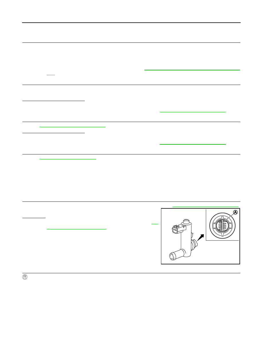
1.
CHECK EVAP CANISTER VENT CONTROL VALVE-I
1. Remove EVAP canister vent control valve from EVAP canister. Refer to
FL-16, "Removal and Installation"
.
2. Check portion (A) of EVAP canister vent control valve for rust.
Is it rusted?
YES
>> Replace EVAP canister vent control valve. Refer to
16, "Removal and Installation"
.
NO
>> GO TO 2.
2.
CHECK EVAP CANISTER VENT CONTROL VALVE-II
With CONSULT
1. Reconnect harness connectors disconnected.
2. Turn ignition switch ON.
3. Perform “VENT CONTROL/V” in “ACTIVE TEST” mode.
JMBIA0168ZZ