Nissan Maxima. Manual - part 462


  Index      Nissan     Nissan Maxima (2009-2014 year) - Service and Repair Manual


Search            


Content   ..  460  461  462  463   ..


Nissan Maxima. Manual - part 462


EC-332

< DTC/CIRCUIT DIAGNOSIS >

[VQ35DE]

P0444, P0445 EVAP CANISTER PURGE VOLUME CONTROL SOLENOID 

VALVE

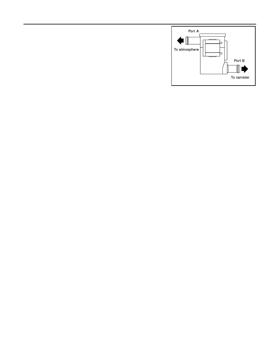
4. Blow air into port A and check that it flows freely out of port B.
5. Block port B.
6. Blow air into port A and check that there is no leakage.
7. If NG, replace drain filter.

PBIB3641E

P0447 EVAP CANISTER VENT CONTROL VALVE

EC-333

< DTC/CIRCUIT DIAGNOSIS >

[VQ35DE]

C

D

E

F

G

H

I

J

K

L

M

A

EC

N

P

O

P0447 EVAP CANISTER VENT CONTROL VALVE

Description

INFOID:0000000010095016

The EVAP canister vent control valve is located on the EVAP canis-

ter and is used to seal the canister vent.

This solenoid valve responds to signals from the ECM. When the

ECM sends an ON signal, the coil in the solenoid valve is energized.

A plunger will then move to seal the canister vent. The ability to seal

the vent is necessary for the on board diagnosis of other evaporative

emission control system components.

This solenoid valve is used only for diagnosis, and usually remains

opened.

When the vent is closed, under normal purge conditions, the evapo-

rative emission control system is depressurized and allows “EVAP

Control System” diagnosis.

DTC Logic

INFOID:0000000010095017

DTC DETECTION LOGIC

DTC CONFIRMATION PROCEDURE

1.

PRECONDITIONING

If DTC Confirmation Procedure has been previously conducted, always perform the following before conduct-

ing the next test.

1. Turn ignition switch OFF and wait at least 10 seconds.

2. Turn ignition switch ON.

3. Turn ignition switch OFF and wait at least 10 seconds.

TESTING CONDITION:

Before performing the following procedure, confirm battery voltage is more than 11 V at idle.

>> GO TO 2.

2.

PERFORM DTC CONFIRMATION PROCEDURE

1. Start engine and wait at least 8 seconds.

2. Check 1st trip DTC.
Is 1st trip DTC detected?

YES

>> Go to 

EC-333, "Diagnosis Procedure"

.

NO

>> INSPECTION END

Diagnosis Procedure

INFOID:0000000010095018

Regarding Wiring Diagram information, refer to 

EC-554, "Wiring Diagram"

.

1.

INSPECTION START

Will CONSULT be used?

YES

>> GO TO 2.

NO

>> GO TO 3.

PBIB1263E

DTC No.

Trouble diagnosis name

DTC detecting condition

Possible cause

P0447

EVAP canister vent con-
trol valve circuit open

An improper voltage signal is sent to ECM via 
the EVAP canister vent control valve.

• Harness or connectors

(The valve circuit is open or shorted.)

• EVAP canister vent control valve
• Hoses

(Hoses are connected incorrectly or 
clogged.)

• Drain filter

EC-334

< DTC/CIRCUIT DIAGNOSIS >

[VQ35DE]

P0447 EVAP CANISTER VENT CONTROL VALVE

2.

CHECK EVAP CANISTER VENT CONTROL VALVE CIRCUIT

With CONSULT

1. Turn ignition switch OFF and then ON.

2. Select “VENT CONTROL/V” in “ACTIVE TEST” mode with CONSULT.

3. Touch “ON/OFF” on CONSULT screen.

4. Check for operating sound of the valve.

Is the inspection result normal?

YES

>> GO TO 7.

NO

>> GO TO 3.

3.

CHECK EVAP CANISTER VENT CONTROL VALVE POWER SUPPLY CIRCUIT

1. Turn ignition switch OFF.

2. Disconnect EVAP canister vent control valve harness connector.

3. Turn ignition switch ON.

4. Check the voltage between EVAP canister vent control valve

harness connector and ground.

Is the inspection result normal?

YES

>> GO TO 5.

NO

>> GO TO 4.

4.

DETECT MALFUNCTIONING PART

Check the following.

• Harness connectors B10, E29

• Harness connectors E11, F2

• Harness for open or short between EVAP canister vent control valve and IPDM E/R

>> Repair open circuit, short to ground or short to power in harness or connectors.

5.

CHECK EVAP CANISTER VENT CONTROL VALVE OUTPUT SIGNAL CIRCUIT FOR OPEN AND SHORT

1. Turn ignition switch OFF.

2. Disconnect ECM harness connector.

3. Check the continuity between ECM harness connector and EVAP canister vent control valve harness con-

nector.

Refer to Wiring Diagram.

4. Also check harness for short to ground and short to power.
Is the inspection result normal?

YES

>> GO TO 7.

NO

>> GO TO 6.

6.

DETECT MALFUNCTIONING PART

Check the following.

• Harness connectors B10, E29

• Harness for open or short between EVAP canister vent control valve and ECM

Clicking sound should be heard.

EVAP canister vent control valve

Ground

Voltage

Connector

Terminal

B39

1

Ground

Battery voltage

PBIB0080E

EVAP canister vent control valve

ECM

Continuity

Connector

Terminal

Connector

Terminal

B39

2

E10

109

Existed

P0447 EVAP CANISTER VENT CONTROL VALVE

EC-335

< DTC/CIRCUIT DIAGNOSIS >

[VQ35DE]

C

D

E

F

G

H

I

J

K

L

M

A

EC

N

P

O

>> Repair open circuit, short to ground or short to power in harness or connectors.

7.

CHECK RUBBER TUBE FOR CLOGGING

1. Disconnect rubber tube connected to EVAP canister vent control valve.

2. Check the rubber tube for clogging.
Is the inspection result normal?

YES

>> GO TO 8.

NO

>> Clean the rubber tube using an air blower.

8.

CHECK DRAIN FILTER

Refer to 

EC-335, "Component Inspection"

.

Is the inspection result normal?

YES

>> GO TO 9.

NO

>> Replace drain filter.

9.

CHECK EVAP CANISTER VENT CONTROL VALVE

Refer to 

EC-335, "Component Inspection"

.

Is the inspection result normal?

YES

>> GO TO 10.

NO

>> Replace EVAP canister vent control valve. Refer to 

FL-16, "Removal and Installation"

.

10.

CHECK INTERMITTENT INCIDENT

Refer to 

GI-41, "Intermittent Incident"

.

>> INSPECTION END

Component Inspection

INFOID:0000000010095019

EVAP CANISTER VENT CONTROL VALVE

1.

CHECK EVAP CANISTER VENT CONTROL VALVE-I

1. Remove EVAP canister vent control valve from EVAP canister. Refer to 

FL-16, "Removal and Installation"

.

2. Check portion (A) of EVAP canister vent control valve for rust.
Is it rusted?

YES

>> Replace EVAP canister vent control valve. Refer to 

FL-

16, "Removal and Installation"

.

NO

>> GO TO 2.

2.

CHECK EVAP CANISTER VENT CONTROL VALVE-II

With CONSULT

1. Reconnect harness connectors disconnected.

2. Turn ignition switch ON.

3. Perform “VENT CONTROL/V” in “ACTIVE TEST” mode.

JMBIA0168ZZ


Content   ..  460  461  462  463   ..