Nissan Maxima. Manual - part 456
EC-308
< DTC/CIRCUIT DIAGNOSIS >
[VQ35DE]
P0420, P0430 THREE WAY CATALYST FUNCTION
• It might damage the ignition coil if the gap of more than 17 mm (0.66 in) is made.
NOTE:
When the gap is less than 13 mm (0.52 in), a spark might be generated even if the coil is malfunc-
tioning.
Is the inspection result normal?
YES
>> GO TO 10.
NO
>> GO TO 7.
7.
CHECK FUNCTION OF IGNITION COIL-II
1. Turn ignition switch OFF.
2. Disconnect spark plug and connect a non-malfunctioning spark plug.
3. Crank engine for about 3 seconds, and recheck whether spark is generated between the spark plug and
the grounded metal portion.
Is the inspection result normal?
YES
>> GO TO 8.
NO
>> Check ignition coil, power transistor and their circuit. Refer to
8.
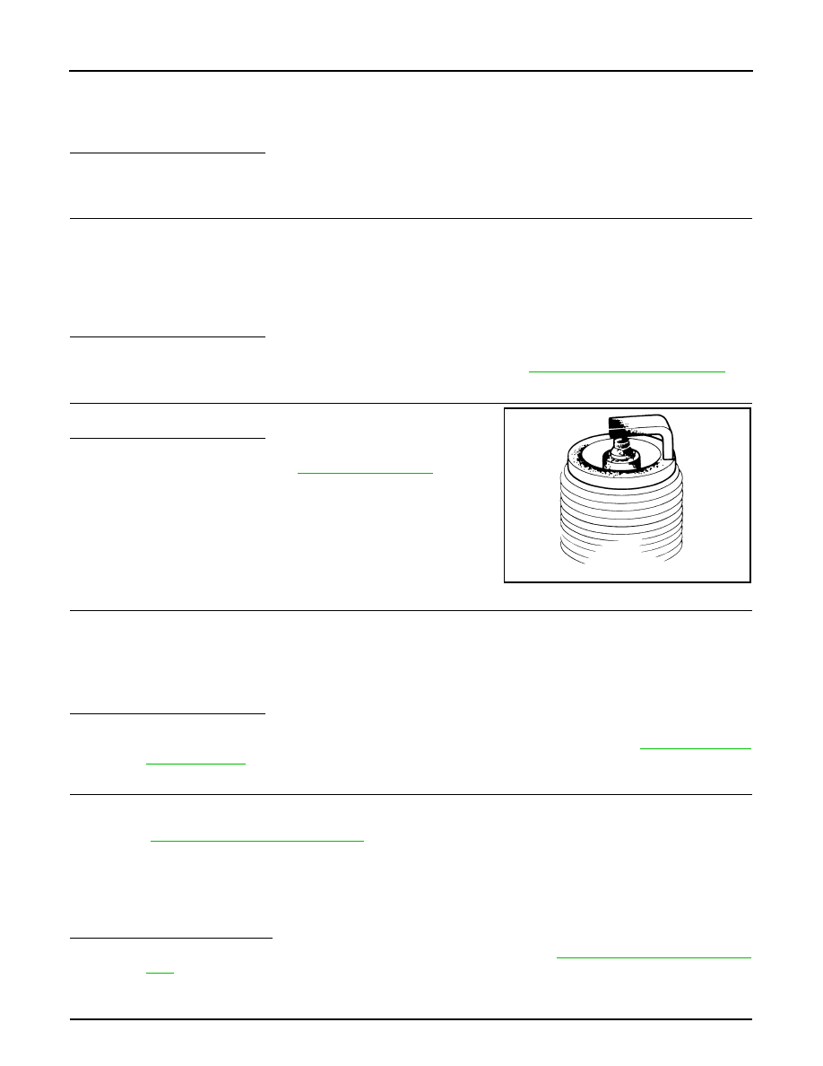
CHECK SPARK PLUG
Check the initial spark plug for fouling, etc.
Is the inspection result normal?
YES
>> Replace spark plug(s) with standard type one(s). For
spark plug type, refer to
.
NO
>> Repair or clean spark plug. Then GO TO 9.
9.
CHECK FUNCTION OF IGNITION COIL-III
1. Reconnect the initial spark plugs.
2. Crank engine for about three seconds, and recheck whether spark is generated between the spark plug
and the grounded portion.
Is the inspection result normal?
YES
>> INSPECTION END
NO
>> Replace spark plug(s) with standard type one(s). For spark plug type, refer to
.
10.
CHECK FUEL INJECTOR
1. Turn ignition switch OFF.
2. Remove fuel injector assembly.
EM-43, "Removal and Installation"
Keep fuel hose and all fuel injectors connected to fuel tube.
3. Disconnect all ignition coil harness connectors.
4. Reconnect all fuel injector harness connectors disconnected.
5. Turn ignition switch ON.
Check that fuel does not drip from fuel injector.
Does fuel drip from fuel injector?
YES
>> Replace the fuel injector(s) from which fuel is dripping. Refer to
.
NO
>> GO TO 11.
11.
CHECK INTERMITTENT INCIDENT
Spark should be generated.
SEF156I
Spark should be generated.