Nissan Maxima. Manual - part 440


  Index      Nissan     Nissan Maxima (2009-2014 year) - Service and Repair Manual


Search            


Content   ..  438  439  440  441   ..


Nissan Maxima. Manual - part 440


EC-244

< DTC/CIRCUIT DIAGNOSIS >

[VQ35DE]

P0138, P0158 HO2S2

15.

CHECK INTERMITTENT INCIDENT

Refer to 

GI-41, "Intermittent Incident"

.

>> INSPECTION END

Component Inspection

INFOID:0000000010094948

1.

INSPECTION START

Will CONSULT be used?

YES

>> GO TO 2.

NO

>> GO TO 3.

2.

CHECK HEATED OXYGEN SENSOR 2

With CONSULT

1. Turn ignition switch ON and select “DATA MONITOR” mode with CONSULT.

2. Start engine and warm it up to the normal operating temperature.

3. Turn ignition switch OFF and wait at least 10 seconds.

4. Start engine and keep the engine speed between 3,500 and 4,000 rpm for at least 1 minute under no load.

5. Let engine idle for 1 minute.

6. Select “FUEL INJECTION” in “ACTIVE TEST” mode, and select “HO2S2 (B1)/(B2)” as the monitor item

with CONSULT.

7. Check “HO2S2 (B1)/(B2)” at idle speed when adjusting “FUEL INJECTION” to 

±25%.

: “HO2S2 (B1)/(B2)” should be above 0.78 V at least once when the “FUEL INJECTION” is +25%.
: “HO2S2 (B1)/(B2)” should be below 0.18 V at least once when the “FUEL INJECTION” is 

25%.

Is the inspection result normal?

YES

>> INSPECTION END

NO

>> GO TO 6.

3.

CHECK HEATED OXYGEN SENSOR 2-I

Without CONSULT

1. Start engine and warm it up to the normal operating temperature.

2. Turn ignition switch OFF and wait at least 10 seconds.

3. Start engine and keep the engine speed between 3,500 and 4,000 rpm for at least 1 minute under no load.

4. Let engine idle for 1 minute.

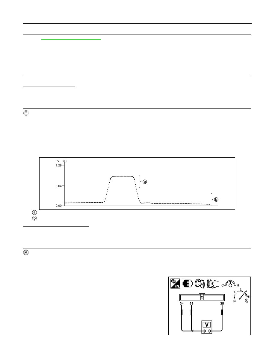
5. Check the voltage between ECM harness connector terminals

under the following conditions.

JSBIA3451ZZ

JMBIA1865ZZ

P0138, P0158 HO2S2

EC-245

< DTC/CIRCUIT DIAGNOSIS >

[VQ35DE]

C

D

E

F

G

H

I

J

K

L

M

A

EC

N

P

O

Is the inspection result normal?

YES

>> INSPECTION END

NO

>> GO TO 4.

4.

CHECK HEATED OXYGEN SENSOR 2-II

Check the voltage between ECM harness connector terminals under

the following conditions.

Is the inspection result normal?

YES

>> INSPECTION END

NO

>> GO TO 5.

5.

CHECK HEATED OXYGEN SENSOR 2-III

Check the voltage between ECM harness connector terminals under

the following conditions.

Is the inspection result normal?

YES

>> INSPECTION END

NO

>> GO TO 6.

6.

REPLACE HEATED OXYGEN SENSOR 2

ECM

Condition

Voltage

Con-

nector

+

Terminal

Terminal

F13

33

[HO2S2 

(bank 1) 

signal]

35

(Sensor 
ground)

Revving up to 4,000 
rpm under no load at 
least 10 times

The voltage should be 
above 0.78 V at least 
once during this proce-
dure.
The voltage should be 
below 0.18 V at least 
once during this proce-
dure.

34

[HO2S2 

(bank 2) 

signal]

ECM

Condition

Voltage

Con-

nector

+

Terminal

Terminal

F13

33

[HO2S2 

(bank 1) 

signal]

35

(Sensor 
ground)

Keeping engine at 
idle for 10 minutes

The voltage should be 
above 0.78 V at least 
once during this proce-
dure.
The voltage should be 
below 0.18 V at least 
once during this proce-
dure.

34

[HO2S2 

(bank 2) 

signal]

JMBIA1866ZZ

ECM

Condition

Voltage

Con-

nector

+

Terminal

Terminal

F13

33

[HO2S2 

(bank 1) 

signal]

35

(Sensor 
ground)

Coasting from 80 km/
h (50 MPH) in D posi-
tion

The voltage should be 
above 0.78 V at least 
once during this proce-
dure.
The voltage should be 
below 0.18 V at least 
once during this proce-
dure.

34

[HO2S2 

(bank 2) 

signal]

JMBIA1867ZZ

EC-246

< DTC/CIRCUIT DIAGNOSIS >

[VQ35DE]

P0138, P0158 HO2S2

Replace malfunctioning heated oxygen sensor 2. Refer to 

EM-31, "Removal and Installation (LH)"

 (LH) or 

EM-

33, "Removal and Installation (RH)"

 (RH).

CAUTION:

• Discard any heated oxygen sensor which has been dropped from a height of more than 0.5 m (19.7

in) onto a hard surface such as a concrete floor; use a new one.

• Before installing new oxygen sensor, clean exhaust system threads using Oxygen Sensor Thread

Cleaner [commercial service tool (J-43897-18 or J-43897-12)] and approved anti-seize lubricant

(commercial service tool).

>> INSPECTION END

P0139, P0159 HO2S2

EC-247

< DTC/CIRCUIT DIAGNOSIS >

[VQ35DE]

C

D

E

F

G

H

I

J

K

L

M

A

EC

N

P

O

P0139, P0159 HO2S2

Description

INFOID:0000000010094949

The heated oxygen sensor 2, after three way catalyst (manifold),

monitors the oxygen level in the exhaust gas on each bank.

Even if switching characteristics of the air fuel ratio (A/F) sensor 1

are shifted, the air-fuel ratio is controlled to stoichiometric, by the sig-

nal from the heated oxygen sensor 2.

This sensor is made of ceramic zirconia. The zirconia generates volt-

age from approximately 1 V in richer conditions to 0 V in leaner con-

ditions.

Under normal conditions the heated oxygen sensor 2 is not used for

engine control operation.

DTC Logic

INFOID:0000000010094950

DTC DETECTION LOGIC

The heated oxygen sensor 2 has a much longer switching time

between rich and lean than the air fuel ratio (A/F) sensor 1. The oxy-

gen storage capacity of the three way catalyst (manifold) causes the

longer switching time. To judge the malfunctions of heated oxygen

sensor 2, ECM monitors whether the switching response of the sen-

sor's voltage is faster than specified during various driving conditions

such as fuel-cut.

DTC CONFIRMATION PROCEDURE

1.

INSPECTION START

Do you have CONSULT?

YES

>> GO TO 2.

NO

>> GO TO 7.

2.

PRECONDITIONING

If DTC Confirmation Procedure has been previously conducted, always perform the following procedure

before conducting the next test.

1. Turn ignition switch OFF and wait at least 10 seconds.

2. Turn ignition switch ON.

3. Turn ignition switch OFF and wait at least 10 seconds.

TESTING CONDITION:

For better results, perform “DTC WORK SUPPORT” at a temperature of 0 to 30

°C (32 to 86°F).

>> GO TO 3.

SEF327R

SEF302U

DTC No.

Trouble diagnosis name

DTC detecting condition

Possible cause

P0139

Heated oxygen sensor 2 
(bank 1) circuit slow re-
sponse

It takes more time for the sensor to respond be-
tween rich and lean than the specified time.

• Harness or connectors

(The sensor circuit is open or shorted.)

• Heated oxygen sensor 2
• Fuel pressure
• Fuel injector
• Intake air leakage

P0159

Heated oxygen sensor 2 
(bank 2) circuit slow re-
sponse


Content   ..  438  439  440  441   ..