Nissan Maxima. Manual - part 425


  Index      Nissan     Nissan Maxima (2009-2014 year) - Service and Repair Manual


Search            


Content   ..  423  424  425  426   ..


Nissan Maxima. Manual - part 425


EC-184

< DTC/CIRCUIT DIAGNOSIS >

[VQ35DE]

P0101 MAF SENSOR

Diagnosis Procedure

INFOID:0000000010094889

1.

CHECK INTAKE SYSTEM

Check the following for connection.

• Air duct

• Vacuum hoses

• Intake air passage between air duct and intake manifold
Is the inspection result normal?

YES

>> GO TO 2.

NO

>> Reconnect the parts.

2.

CHECK GROUND CONNECTION

1. Turn ignition switch OFF.

2. Check ground connection E9. Refer to Ground Inspection in 

GI-44, "Circuit Inspection"

.

Is the inspection result normal?

YES

>> GO TO 3.

NO

>> Repair or replace ground connection.

3.

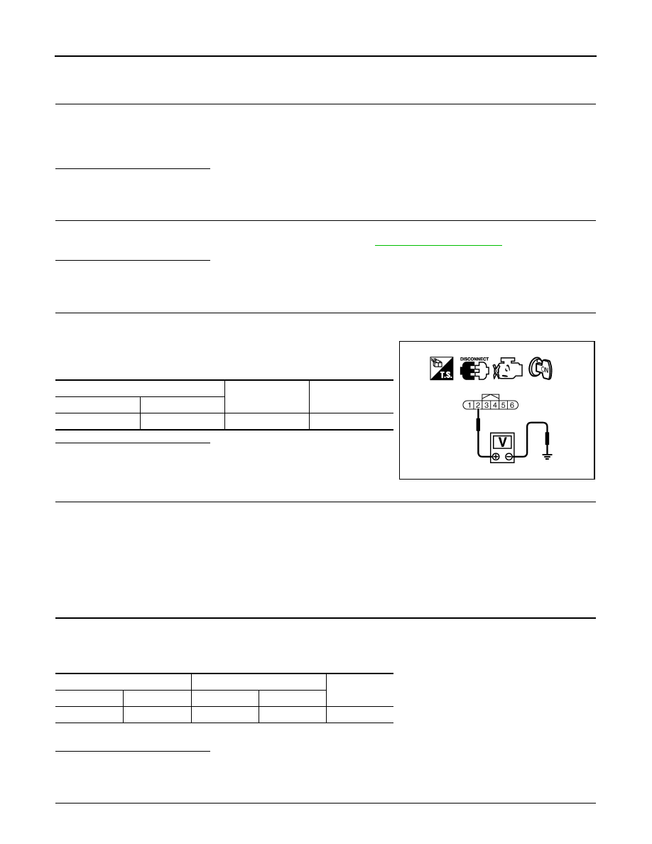
CHECK MASS AIR FLOW (MAF) SENSOR POWER SUPPLY CIRCUIT

1. Disconnect MAF sensor harness connector.

2. Turn ignition switch ON.

3. Check the voltage between MAF sensor harness connector and

ground.

Is the inspection result normal?

YES

>> GO TO 5.

NO

>> GO TO 4.

4.

DETECT MALFUNCTIONING PART

Check the following.

• Harness connectors E11, F2

• Junction block connectors E44, E45

• Harness for open or short between mass air flow sensor and ECM

• Harness for open or short between mass air flow sensor and IPDM E/R

>> Repair open circuit or short to ground or short to power in harness or connectors.

5.

CHECK MAF SENSOR GROUND CIRCUIT FOR OPEN AND SHORT

1. Turn ignition switch OFF.

2. Disconnect ECM harness connector.

3. Check the continuity between MAF sensor harness connector and ECM harness connector.

4. Also check harness for short to ground and short to power.
Is the inspection result normal?

YES

>> GO TO 6.

NO

>> Repair open circuit or short to ground or short to power in harness or connectors.

6.

CHECK MAF SENSOR INPUT SIGNAL CIRCUIT FOR OPEN AND SHORT

MAF sensor

Ground

Voltage

Connector

Terminal

F31

2

Ground

Battery voltage

PBIB1168E

MAF sensor

ECM

Continuity

Connector

Terminal

Connector

Terminal

F31

3

F13

56

Existed

P0101 MAF SENSOR

EC-185

< DTC/CIRCUIT DIAGNOSIS >

[VQ35DE]

C

D

E

F

G

H

I

J

K

L

M

A

EC

N

P

O

1. Check the continuity between MAF sensor harness connector and ECM harness connector.

2. Also check harness for short to ground and short to power.
Is the inspection result normal?

YES

>> GO TO 7.

NO

>> Repair open circuit or short to ground or short to power in harness or connectors.

7.

CHECK INTAKE AIR TEMPERATURE SENSOR

Check intake air temperature sensor. Refer to 

EC-185, "Component Inspection"

.

Is the inspection result normal?

YES

>> GO TO 8.

NO

>> Replace MAF sensor (with intake air temperature sensor). Refer to 

EM-24, "Removal and Installa-

tion"

.

8.

CHECK EVAP CONTROL SYSTEM PRESSURE SENSOR

Check EVAP control system pressure sensor. Refer to 

EC-346, "Component Inspection"

.

Is the inspection result normal?

YES

>> GO TO 9.

NO

>> Replace EVAP control system pressure sensor.

9.

CHECK MAF SENSOR

Check MAF sensor. Refer to 

EC-185, "Component Inspection"

.

Is the inspection result normal?

YES

>> GO TO 10.

NO

>> Replace MAF sensor. Refer to 

EM-24, "Removal and Installation"

.

10.

CHECK INTERMITTENT INCIDENT

Check intermittent incident. Refer to 

GI-41, "Intermittent Incident"

.

>> INSPECTION END

Component Inspection

INFOID:0000000010094890

1.

CHECK MASS AIR FLOW SENSOR-I

With CONSULT

1. Reconnect all harness connectors disconnected.

2. Start engine and warm it up to normal operating temperature.

3. Connect CONSULT and select “DATA MONITOR” mode.

4. Select “MAS A/F SE-B1” and check indication under the following conditions.

*: Check for linear voltage rise in response to engine being increased to about 4,000 rpm.

Without CONSULT

1. Reconnect all harness connectors disconnected.

2. Start engine and warm it up to normal operating temperature.

MAF sensor

ECM

Continuity

Connector

Terminal

Connector

Terminal

F31

4

F13

58

Existed

Monitor item

Condition

MAS A/F SE-B1 (V)

MAS A/F SE-B1

Ignition switch ON (Engine stopped.)

Approx. 0.4

Idle (Engine is warmed-up to normal operating temperature.)

0.9 - 1.2

2,500 rpm (Engine is warmed-up to normal operating temperature.)

1.6 - 1.9

Idle to about 4,000 rpm

0.9 - 1.2 to Approx. 2.4*

EC-186

< DTC/CIRCUIT DIAGNOSIS >

[VQ35DE]

P0101 MAF SENSOR

3. Check the voltage between ECM harness connector terminals

under the following conditions.

*: Check for linear voltage rise in response to engine being increased to about 4,000 rpm.

Is the inspection result normal?

YES

>> INSPECTION END

NO

>> GO TO 2.

2.

CHECK FOR THE CAUSE OF UNEVEN AIR FLOW VIA THE MASS AIR FLOW SENSOR

Check for the cause of uneven air flow via the mass air flow sensor. Refer to the following.

• Crushed air ducts

• Malfunctioning seal of air cleaner element

• Uneven dirt of air cleaner element

• Improper specification of intake air system parts
Is the inspection result normal?

YES

>> GO TO 4.

NO

>> GO TO 3.

3.

CHECK MASS AIR FLOW SENSOR-II

With CONSULT

1. Repair or replace malfunctioning part.

2. Start engine and warm it up to normal operating temperature.

3. Connect CONSULT and select “DATA MONITOR” mode.

4. Select “MAS A/F SE-B1” and check indication under the following conditions.

*: Check for linear voltage rise in response to engine being increased to about 4,000 rpm.

Without CONSULT

1. Repair or replace malfunctioning part.

2. Start engine and warm it up to normal operating temperature.

ECM

Condition

Voltage (V)

Con-

nector

+

Terminal

Terminal

F13

58

(MAF 

sensor 
signal)

56

(Sensor 
ground)

Ignition switch ON (Engine 
stopped.)

Approx. 0.4

Idle (Engine is warmed-up to normal 
operating temperature.)

0.9 - 1.2

2,500 rpm (Engine is warmed-up to 
normal operating temperature.)

1.6 - 1.9

Idle to about 4,000 rpm

0.9 - 1.2 to 

Approx. 2.4*

JMBIA1862ZZ

Monitor item

Condition

MAS A/F SE-B1 (V)

MAS A/F SE-B1

Ignition switch ON (Engine stopped.)

Approx. 0.4

Idle (Engine is warmed-up to normal operating temperature.)

0.9 - 1.2

2,500 rpm (Engine is warmed-up to normal operating temperature.)

1.6 - 1.9

Idle to about 4,000 rpm

0.9 - 1.2 to Approx. 2.4*

P0101 MAF SENSOR

EC-187

< DTC/CIRCUIT DIAGNOSIS >

[VQ35DE]

C

D

E

F

G

H

I

J

K

L

M

A

EC

N

P

O

3. Check the voltage between ECM harness connector terminals

under the following conditions.

*: Check for linear voltage rise in response to engine being increased to about 4,000 rpm.

Is the inspection result normal?

YES

>> INSPECTION END

NO

>> GO TO 4.

4.

CHECK MASS AIR FLOW SENSOR-III

With CONSULT

1. Turn ignition switch OFF.

2. Disconnect mass air flow sensor harness connector and reconnect it again.

3. Start engine and warm it up to normal operating temperature.

4. Connect CONSULT and select “DATA MONITOR” mode.

5. Select “MAS A/F SE-B1” and check indication under the following conditions.

*: Check for linear voltage rise in response to engine being increased to about 4,000 rpm.

Without CONSULT

1. Turn ignition switch OFF.

2. Disconnect mass air flow sensor harness connector and reconnect it again.

3. Start engine and warm it up to normal operating temperature.

4. Check the voltage between ECM harness connector terminals

under the following conditions.

*: Check for linear voltage rise in response to engine being increased to about 4,000 rpm.

Is the inspection result normal?

ECM

Condition

Voltage (V)

Con-

nector

+

Terminal

Terminal

F13

58

(MAF 

sensor 
signal)

56

(Sensor 
ground)

Ignition switch ON (Engine 
stopped.)

Approx. 0.4

Idle (Engine is warmed-up to normal 
operating temperature.)

0.9 - 1.2

2,500 rpm (Engine is warmed-up to 
normal operating temperature.)

1.6 - 1.9

Idle to about 4,000 rpm

0.9 - 1.2 to 

Approx. 2.4*

JMBIA1862ZZ

Monitor item

Condition

MAS A/F SE-B1 (V)

MAS A/F SE-B1

Ignition switch ON (Engine stopped.)

Approx. 0.4

Idle (Engine is warmed-up to normal operating temperature.)

0.9 - 1.2

2,500 rpm (Engine is warmed-up to normal operating temperature.)

1.6 - 1.9

Idle to about 4,000 rpm

0.9 - 1.2 to Approx. 2.4*

ECM

Condition

Voltage (V)

Con-

nector

+

Terminal

Terminal

F13

58

(MAF 

sensor 
signal)

56

(Sensor 
ground)

Ignition switch ON (Engine 
stopped.)

Approx. 0.4

Idle (Engine is warmed-up to normal 
operating temperature.)

0.9 - 1.2

2,500 rpm (Engine is warmed-up to 
normal operating temperature.)

1.6 - 1.9

Idle to about 4,000 rpm

0.9 - 1.2 to 

Approx. 2.4*

JMBIA1862ZZ


Content   ..  423  424  425  426   ..