Nissan Maxima. Manual - part 421


  Index      Nissan     Nissan Maxima (2009-2014 year) - Service and Repair Manual


Search            


Content   ..  419  420  421  422   ..


Nissan Maxima. Manual - part 421


EC-168

< DTC/CIRCUIT DIAGNOSIS >

[VQ35DE]

P0014, P0024 EVT CONTROL

>> INSPECTION END

4.

CHECK EVT CONTROL POSITION SENSOR

Refer to 

EC-402, "Component Inspection"

.

Is the inspection result normal?

YES

>> GO TO 5.

NO

>> Replace malfunctioning EVT control position sensor. Refer to 

EM-48, "Exploded View"

.

5.

CHECK CRANKSHAFT POSITION SENSOR

Refer to 

EC-299, "Component Inspection"

.

Is the inspection result normal?

YES

>> GO TO 6.

NO

>> Replace crankshaft position sensor. Refer to 

EM-37, "Removal and Installation (Upper Oil Pan)"

.

6.

CHECK CAMSHAFT POSITION SENSOR

Refer to 

EM-37, "Removal and Installation (Upper Oil Pan)"

.

Is the inspection result normal?

YES

>> GO TO 7.

NO

>> Replace malfunctioning camshaft position sensor. Refer to 

EM-48, "Exploded View"

.

7.

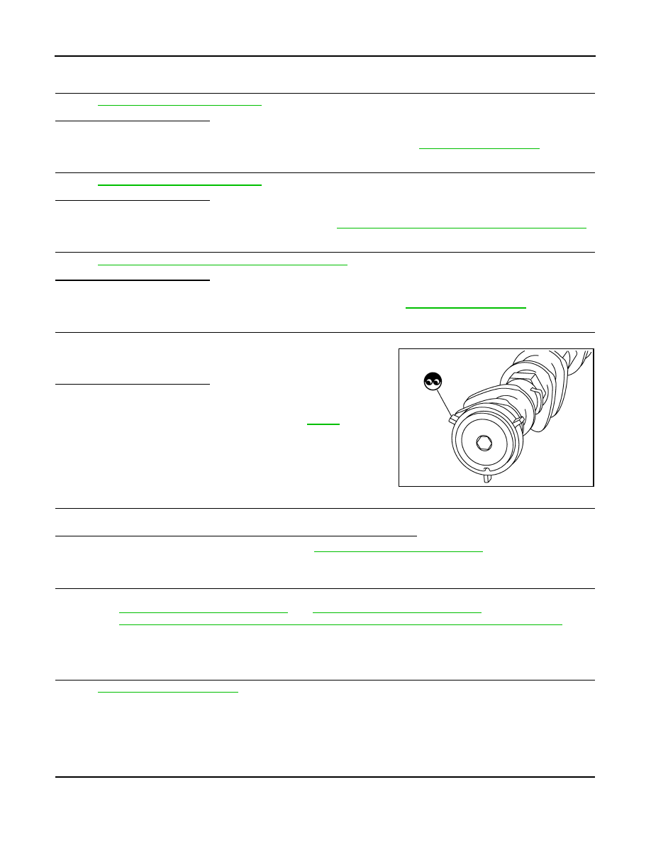
CHECK CAMSHAFT (EXH)

Check the following.

• Accumulation of debris to the signal plate of camshaft rear end

• Chipping signal plate of camshaft rear end
Is the inspection result normal?

YES

>> GO TO 8.

NO

>> Remove debris and clean the signal plate of camshaft

rear end or replace camshaft. Refer to 

EM-76

.

8.

CHECK TIMING CHAIN INSTALLATION

Check service records for any recent repairs that may cause timing chain misalignment.
Are there any service records that may cause timing chain misalignment?

YES

>> Check timing chain installation. Refer to 

EM-64, "Removal and Installation"

.

NO

>> GO TO 9.

9.

REPLACE EVT CONTROL PULLEY ASSEMBLY

1. Replace camshaft sprocket (EXH) and EVT control magnet retarder.

Refer to 

EM-64, "Removal and Installation"

 and 

EM-54, "Removal and Installation"

.

2. Perform 

EC-23, "EXHAUST VALVE TIMING CONTROL LEARNING : Special Repair Requirement"

.

>> INSPECTION END

10.

CHECK INTERMITTENT INCIDENT

Refer to 

GI-41, "Intermittent Incident"

.

>> INSPECTION END

Component Inspection

INFOID:0000000010094870

1.

CHECK EXHAUST VALVE TIMING CONTROL MAGNET RETARDER

1. Turn ignition switch OFF.

2. Disconnect exhaust valve timing control magnet retarder harness connector.

JMBIA0059ZZ

P0014, P0024 EVT CONTROL

EC-169

< DTC/CIRCUIT DIAGNOSIS >

[VQ35DE]

C

D

E

F

G

H

I

J

K

L

M

A

EC

N

P

O

3. Check resistance between exhaust valve timing control magnet

retarder terminals as per the following.

Is the inspection result normal?

YES

>> INSPECTION END

NO

>> GO TO 2.

2.

REPLACE EXHAUST VALVE TIMING CONTROL MAGNET RETARDER

1. Replace malfunctioning exhaust valve timing control magnet retarder. Refer to 

EM-54, "Removal and

Installation"

.

2. Perform 

EC-23, "EXHAUST VALVE TIMING CONTROL LEARNING : Special Repair Requirement"

.

>> INSPECTION END

Terminals

Resistance

1 and 2

9.0 - 11.0 

Ω [at 20°C (68°F)]

PBIB3469E

EC-170

< DTC/CIRCUIT DIAGNOSIS >

[VQ35DE]

P0031, P0032, P0051, P0052 A/F SENSOR 1 HEATER

P0031, P0032, P0051, P0052 A/F SENSOR 1 HEATER

Description

INFOID:0000000010094871

SYSTEM DESCRIPTION

The ECM performs ON/OFF duty control of the A/F sensor 1 heater corresponding to the engine operating

condition to keep the temperature of A/F sensor 1 element within the specified range.

DTC Logic

INFOID:0000000010094872

DTC DETECTION LOGIC

DTC CONFIRMATION PROCEDURE

1.

PRECONDITIONING

If DTC Confirmation Procedure has been previously conducted, always perform the following before conduct-

ing the next test.

1. Turn ignition switch OFF and wait at least 10 seconds.

2. Turn ignition switch ON.

3. Turn ignition switch OFF and wait at least 10 seconds.

TESTING CONDITION:

Before performing the following procedure, confirm that battery voltage is more than 11 V at idle.

>> GO TO 2.

2.

PERFORM DTC CONFIRMATION PROCEDURE

1. Start engine and let it idle for at least 10 seconds.

2. Check 1st trip DTC.
Is 1st trip DTC detected?

YES

>> Go to 

EC-170, "Diagnosis Procedure"

.

NG

>> INSPECTION END

Diagnosis Procedure

INFOID:0000000010094873

Regarding Wiring Diagram information, refer to 

EC-554, "Wiring Diagram"

.

Sensor

Input Signal to ECM

ECM function

Actuator

Camshaft position sensor (PHASE)
Crankshaft position sensor (POS)

Engine speed

Air fuel ratio (A/F) sensor 1 
heater control

Air fuel ratio (A/F) sensor 1 
heater

Mass air flow sensor

Amount of intake air

DTC No.

Trouble diagnosis name

DTC detecting condition

Possible cause

P0031

Air fuel ratio (A/F) sensor 
1 heater (bank 1) control 
circuit low

The current amperage in the A/F sensor 1 heater 
circuit is out of the normal range.
(An excessively low voltage signal is sent to ECM 
via the A/F sensor 1 heater.)

• Harness or connectors

(The A/F sensor 1 heater circuit is 
open or shorted.)

• A/F sensor 1 heater

P0032

Air fuel ratio (A/F) sensor 
1 heater (bank 1) control 
circuit high

The current amperage in the A/F sensor 1 heater 
circuit is out of the normal range.
(An excessively high voltage signal is sent to ECM 
via the A/F sensor 1 heater.) 

• Harness or connectors

(The A/F sensor 1 heater circuit is 
shorted.)

• A/F sensor 1 heater

P0051

Air fuel ratio (A/F) sensor 
1 heater (bank 2) control 
circuit low

The current amperage in the A/F sensor 1 heater 
circuit is out of the normal range.
(An excessively low voltage signal is sent to ECM 
via the A/F sensor 1 heater.)

• Harness or connectors

(The A/F sensor 1 heater circuit is 
open or shorted.)

• A/F sensor 1 heater

P0052

Air fuel ratio (A/F) sensor 
1 heater (bank 2) control 
circuit high

The current amperage in the A/F sensor 1 heater 
circuit is out of the normal range.
(An excessively high voltage signal is sent to ECM 
via the A/F sensor 1 heater.)

• Harness or connectors

(The A/F sensor 1 heater circuit is 
shorted.)

• A/F sensor 1 heater

P0031, P0032, P0051, P0052 A/F SENSOR 1 HEATER

EC-171

< DTC/CIRCUIT DIAGNOSIS >

[VQ35DE]

C

D

E

F

G

H

I

J

K

L

M

A

EC

N

P

O

1.

CHECK GROUND CONNECTION

1. Turn ignition switch OFF.

2. Check ground connection E9. Refer to Ground Inspection in 

GI-44, "Circuit Inspection"

.

Is the inspection result normal?

YES

>> GO TO 2.

NO

>> Repair or replace ground connection.

2.

CHECK AIR FUEL RATIO (A/F) SENSOR 1 POWER SUPPLY CIRCUIT

1. Disconnect air fuel ratio (A/F) sensor 1 harness connector.

2. Turn ignition switch ON.

3. Check the voltage between A/F sensor 1 harness connector and

ground.

Is the inspection result normal?

YES

>> GO TO 4.

NO

>> GO TO 3.

3.

DETECT MALFUNCTIONING PART

Check the following.

• IPDM E/R harness connector F10

• 15 A fuse (No. 37)

• Harness for open or short between A/F sensor 1 and fuse

>> Repair or replace harness or connectors.

4.

CHECK A/F SENSOR 1 HEATER OUTPUT SIGNAL CIRCUIT

1. Turn ignition switch OFF.

2. Disconnect ECM harness connector.

3. Check harness continuity between A/F sensor 1 harness connector and ECM harness connector.

4. Also check harness for short to ground and short to power.
Is the inspection result normal?

YES

>> GO TO 5.

NO

>> Repair open circuit, short to ground or short to power in harness or connectors.

5.

CHECK A/F SENSOR 1 HEATER

Refer to 

EC-172, "Component Inspection"

.

Is the inspection result normal?

YES

>> GO TO 7.

NO

>> GO TO 6.

6.

REPLACE AIR FUEL RATIO (A/F) SENSOR 1

Replace malfunctioning air fuel ratio (A/F) sensor 1. Refer to 

EM-31, "Removal and Installation (LH)"

 or 

EM-

33, "Removal and Installation (RH)"

 (RH).

CAUTION:

DTC

A/F sensor 1

Ground

Voltage

Bank

Connector

Terminal

P0031, P0032

1

F12

4

Ground

Battery voltage

P0051, P0052

2

F61

4

PBIB3308E

DTC

A/F sensor 1

ECM 

Continuity

Bank

Connector

Terminal

Connector

Terminal

P0031, P0032

1

F12

3

F14

4

Existed

P0051, P0052

2

F61

3

8


Content   ..  419  420  421  422   ..