Nissan Maxima. Manual - part 420
EC-164
< DTC/CIRCUIT DIAGNOSIS >
[VQ35DE]
P0011, P0021 IVT CONTROL
Check the following.
• Accumulation of debris on the signal plate of camshaft rear end
• Chipping signal plate of camshaft rear end
Is the inspection result normal?
YES
>> GO TO 6.
NO
>> Remove debris and clean the signal plate of camshaft
rear end or replace camshaft. Refer to
6.
CHECK TIMING CHAIN INSTALLATION
Check service records for any recent repairs that may cause timing chain misalignment.
Are there any service records that may cause timing chain misalignment?
YES
>> Check timing chain installation. Refer to
.
NO
>> GO TO 7.
7.
CHECK LUBRICATION CIRCUIT
Is the inspection result normal?
YES
>> GO TO 8.
NO
>> Clean lubrication line.
8.
CHECK INTERMITTENT INCIDENT
GI-41, "Intermittent Incident"
>> INSPECTION END
Component Inspection
INFOID:0000000010094867
1.
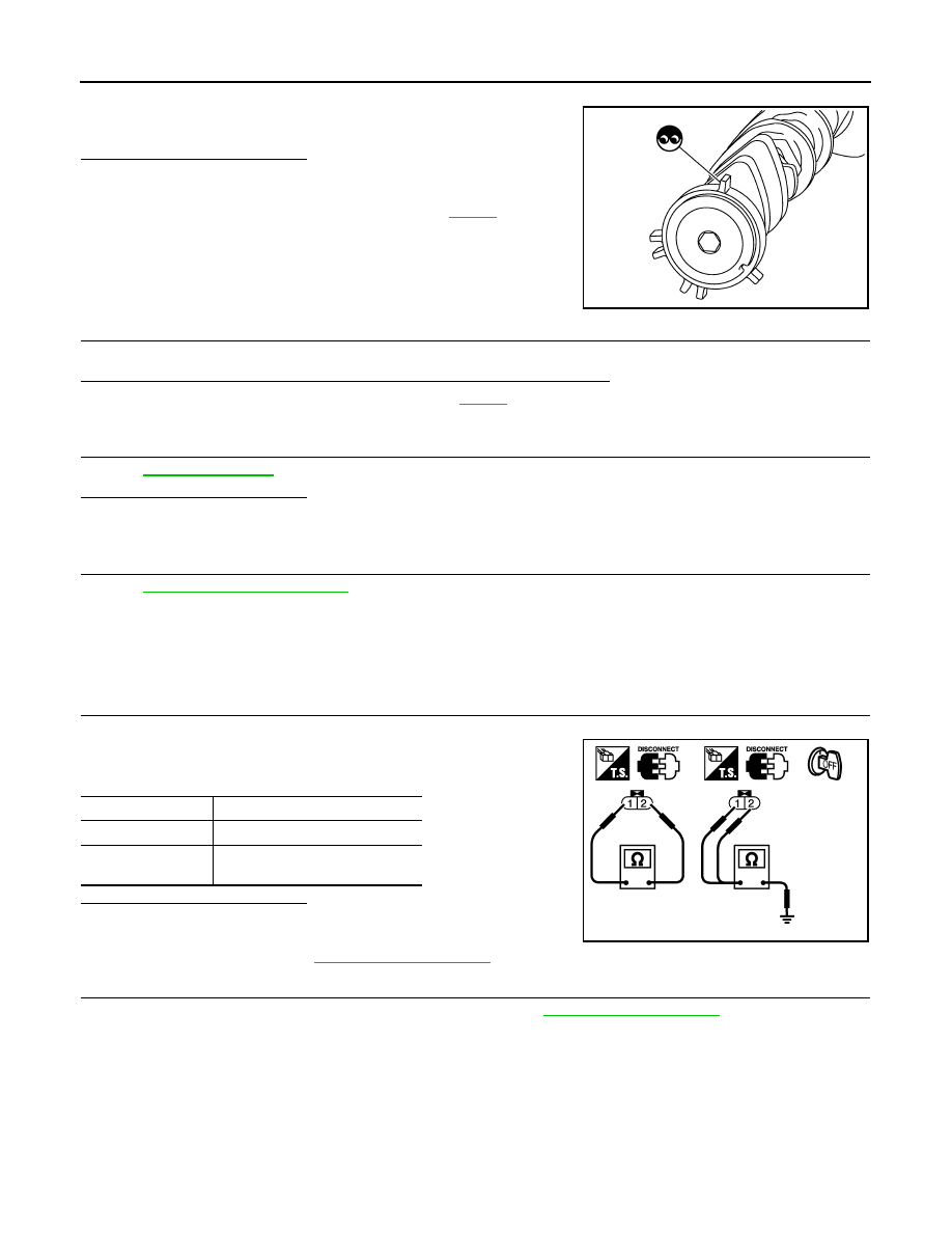
CHECK INTAKE VALVE TIMING CONTROL SOLENOID VALVE-I
1. Disconnect intake valve timing control solenoid valve harness connector.
2. Check resistance between intake valve timing control solenoid
valve terminals as per the following.
Is the inspection result normal?
YES
>> GO TO 2.
NO
>> Replace malfunctioning intake valve timing control sole-
noid valve. Refer to
2.
CHECK INTAKE VALVE TIMING CONTROL SOLENOID VALVE-II
1. Remove intake valve timing control solenoid valve. Refer to
JMBIA0058ZZ
Terminals
Resistance
1 and 2
7.0 - 7.5
Ω [at 20°C (68°F)]
1 or 2 and ground
∞Ω
(Continuity should not exist)
PBIB0193E