Nissan Maxima. Manual - part 394


  Index      Nissan     Nissan Maxima (2009-2014 year) - Service and Repair Manual


Search            


Content   ..  392  393  394  395   ..


Nissan Maxima. Manual - part 394


EC-60

< SYSTEM DESCRIPTION >

[VQ35DE]

ELECTRIC IGNITION SYSTEM

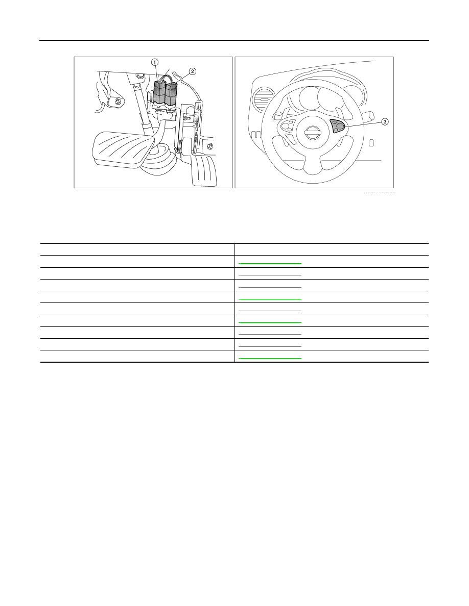
Component Description

INFOID:0000000010094808

1.

Stop lamp switch

2.

ASCD brake switch

3.

ASCD steering switch

AWBIA0670ZZ

Component

Reference

Accelerator pedal position sensor

EC-467, "Description"

Camshaft position sensor (PHASE)

EC-300, "Description"

Crankshaft position sensor (POS)

EC-296, "Description"

Engine coolant temperature sensor

EC-201, "Description"

Ignition signal

EC-502, "Description"

Knock sensor

EC-293, "Description"

Mass air flow sensor

EC-183, "Description"

TCM

EC-397, "Description"

Throttle position sensor

EC-207, "Description"

AIR CONDITIONING CUT CONTROL

EC-61

< SYSTEM DESCRIPTION >

[VQ35DE]

C

D

E

F

G

H

I

J

K

L

M

A

EC

N

P

O

AIR CONDITIONING CUT CONTROL

System Diagram

INFOID:0000000010094809

System Description

INFOID:0000000010094810

INPUT/OUTPUT SIGNAL CHART

*1: This signal is sent to the ECM via the CAN communication line.
*2: ECM determines the start signal status by the signals of engine speed and battery voltage.

SYSTEM DESCRIPTION

This system improves engine operation when the air conditioner is used.

Under the following conditions, the air conditioner is turned OFF.

• When the accelerator pedal is fully depressed.

• When cranking the engine.

• At high engine speeds.

• When the engine coolant temperature becomes excessively high.

• When operating power steering during low engine speed or low vehicle speed.

• When engine speed is excessively low.

• When refrigerant pressure is excessively low or high.

JMBIA1528GB

Sensor

Input Signal to ECM

ECM function

Actuator

Accelerator pedal position sensor

Accelerator pedal position

Air conditioner 
cut control

IPDM E/R

Air conditioner relay

Compressor

Crankshaft position sensor (POS)
Camshaft position sensor (PHASE)

Engine speed*

2

Engine coolant temperature sensor

Engine coolant temperature

Battery

Battery voltage*

2

Refrigerant pressure sensor

Refrigerant pressure

Power steering pressure sensor

Power steering operation

Unified meter and A/C amp.

Air conditioner ON signal*

1

Vehicle speed*

1

EC-62

< SYSTEM DESCRIPTION >

[VQ35DE]

AIR CONDITIONING CUT CONTROL

Component Parts Location

INFOID:0000000010094811

1.

Intake valve timing control solenoid 
valve (bank 1)

2.

Electronic controlled engine mount 
control solenoid valve

3.

Exhaust valve timing control magnet 
retarder (bank 2)

4.

Intake valve timing control solenoid 
valve (bank 2)

5.

Knock sensor (bank 1 and 2) 

6.

Fuel injector (bank 2)

7.

Ignition coil (with power transistor) and 
spark plug (bank 2)

8.

Exhaust valve timing control position 
sensor (bank 2)

9.

Crankshaft position sensor (POS)

10. Engine coolant temperature sensor

11. Camshaft position sensor (PHASE) 

(bank 2)

12. Transmission range switch

13. Refrigerant pressure sensor

14. ECM

15. Battery current sensor

16. Condenser-2

17. EVAP canister purge volume control 

solenoid valve

18. Mass air flow sensor (with intake air 

temperature sensor)

19. Camshaft position sensor (PHASE) 

(bank 1)

20. EVAP service port

21. Power valve actuator 2

22. Electric throttle control actuator

23. Exhaust valve timing control position 

sensor (bank 1)

24. Ignition coil (with power transistor) and 

spark plug (bank 1)

25. Fuel injector (bank 1)

26. VIAS control solenoid valve 1 and 2

27. Power valve actuator 1

28. Exhaust valve timing control magnet 

retarder (bank 1)

29. Power steering pressure sensor

ALBIA0603ZZ

AIR CONDITIONING CUT CONTROL

EC-63

< SYSTEM DESCRIPTION >

[VQ35DE]

C

D

E

F

G

H

I

J

K

L

M

A

EC

N

P

O

1.

Mas air flow sensor (with intake air 
temperature sensor)

2.

Air cleaner case

3.

Engine coolant temperature sensor 
(view with engine cover removed)

4.

EVAP canister purge volume control 
solenoid valve (view with engine cover 
removed)

5.

Power valve actuator 1 (view with en-
gine cover removed)

6.

VIAS control solenoid valve 1

7.

VIAS control solenoid valve 2

8.

Power valve actuator 2

9.

Power steering pressure sensor

10. Tie rod (RH)

11. Camshaft position sensor (PHASE) 

(bank 1) (view with air cleaner case re-
moved)

12. Exhaust valve timing control position 

sensor (bank 1)

13. Camshaft position sensor (PHASE) 

(bank 2) (view with air cleaner case re-
moved)

14. Exhaust valve timing control position 

sensor (bank 2)

15. Engine oil temperature sensor

: Vehicle front

ALBIA0604ZZ


Content   ..  392  393  394  395   ..