Nissan Maxima. Manual - part 303


  Index      Nissan     Nissan Maxima (2009-2014 year) - Service and Repair Manual


Search            


Content   ..  301  302  303  304   ..


Nissan Maxima. Manual - part 303


CO-24

< REMOVAL AND INSTALLATION >

[VQ35DE]

WATER OUTLET AND WATER PIPING

WATER OUTLET AND WATER PIPING

Removal and Installation

INFOID:0000000009469272

WARNING:

Do not remove the radiator cap when the engine is hot. Serious burns could occur from high pressure

engine coolant escaping from the radiator. Wrap a thick cloth around the radiator cap. Slowly turn it a

quarter of a turn to release built-up pressure. Carefully remove radiator cap by turning it all the way.

NOTE:

When removing components such as hoses, tubes/lines, etc., cap or plug openings to prevent fluid from spill-

ing.

REMOVAL

CAUTION:

Perform when the engine is cold.
1. Partially drain coolant from radiator. Refer to 

CO-11, "Changing Engine Coolant"

.

2. Remove engine room cover. Refer to 

EM-23, "Removal and Installation"

3. Remove front air duct and air cleaner case assembly. Refer to 

EM-24, "Removal and Installation"

.

4. Disconnect electric throttle control actuator coolant hoses.
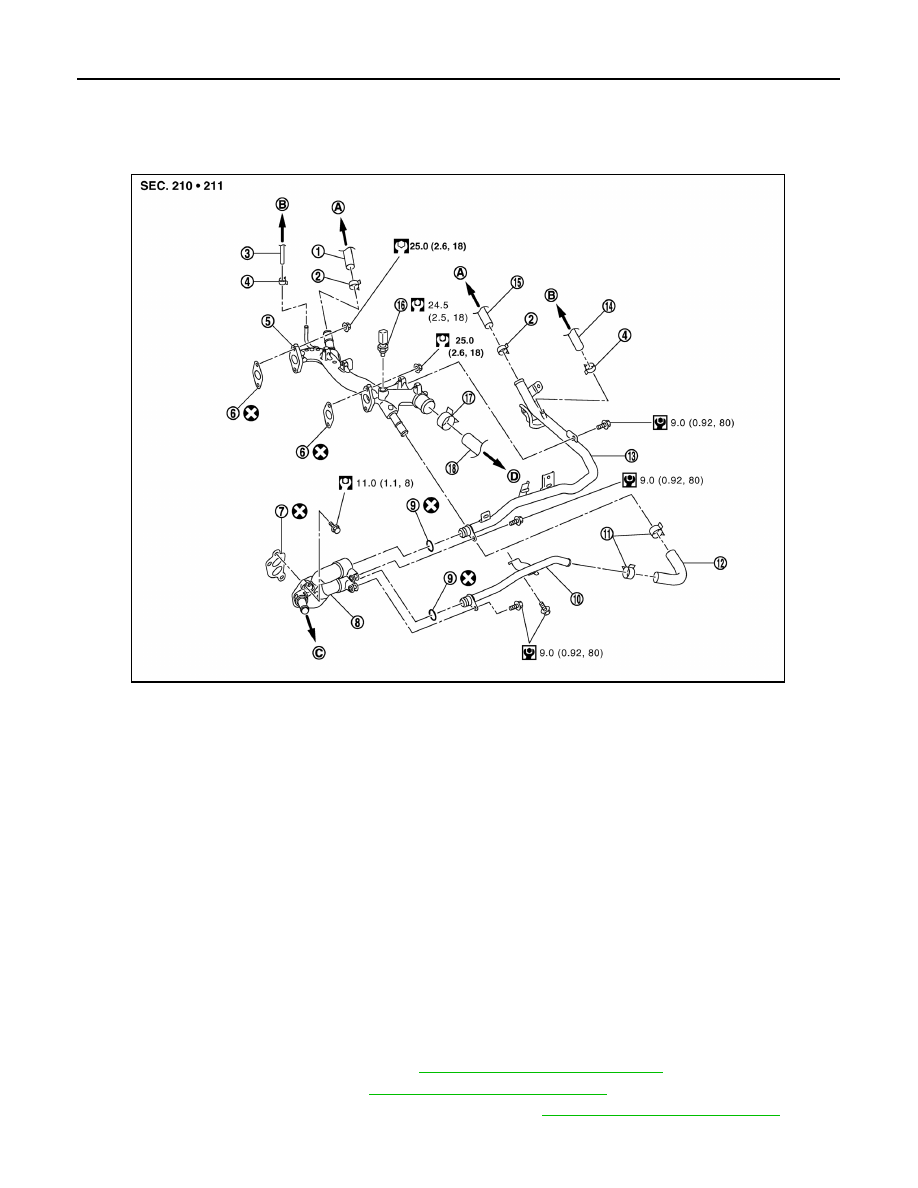
1.

Heater hose

2.

Clamp

3.

Water hose

4.

Clamp

5.

Water outlet

6.

Gasket

7.

Gasket

8.

Water connector

9.

O-ring

10. Water bypass pipe

11. Clamp

12. Water hose

13. Heater pipe

14. Water hose

15. Heater hose

16. Engine coolant temperature sensor

17. Clamp

18. Radiator hose (upper)

A.

To heater core

B.

To electric throttle control actuator

C.

To oil cooler

D.

To radiator

AWBIA1410ZZ

WATER OUTLET AND WATER PIPING

CO-25

< REMOVAL AND INSTALLATION >

[VQ35DE]

C

D

E

F

G

H

I

J

K

L

M

A

CO

N

P

O

5. Remove radiator hose (upper) and both heater hoses.
6. Remove connector(s) from heater pipe.
7. Remove engine coolant temperature sensor on water outlet.
8. Remove water outlet, heater pipe, water connector, and water bypass pipe nuts and bolts.

INSTALLATION

1. Installation is in the reverse order of removal.

• Securely insert each hose, and install a clamp at a position where it does not interfere with the pipe

bulge.

CAUTION:

Do not reuse gasket.

• When inserting heater pipe and water bypass pipe into water connector, apply neutral detergent to new

O-rings.

CAUTION:

Do not reuse O-rings.

• After installation refill engine coolant and check for leaks. Refer to  

CO-11, "Changing Engine Coolant"

and 

CO-10, "System Inspection"

.

CO-26

< UNIT DISASSEMBLY AND ASSEMBLY >

[VQ35DE]

COOLING FAN

UNIT DISASSEMBLY AND ASSEMBLY

COOLING FAN

Disassembly and Assembly of Cooling Fan

INFOID:0000000009469273

DISASSEMBLY

1. Remove fan blade nut.
2. Remove fan blade from fan motor.
3. Remove fan motor bolts and remove fan motor from fan shroud.

ASSEMBLY

Assembly is in the reverse order of disassembly.

AWBIA0739GB

1. Fan blade

2. Fan shroud 

3. Fan motor

SERVICE DATA AND SPECIFICATIONS (SDS)

CO-27

< SERVICE DATA AND SPECIFICATIONS (SDS) 

[VQ35DE]

C

D

E

F

G

H

I

J

K

L

M

A

CO

N

P

O

SERVICE DATA AND SPECIFICATIONS (SDS)

SERVICE DATA AND SPECIFICATIONS (SDS)

Capacity

INFOID:0000000009469274

 (US qt, Imp qt)

Thermostat

INFOID:0000000009469275

Radiator

INFOID:0000000009469276

Unit: kPa (kg/cm

2

, psi)

Coolant capacity (With reservoir tank at MAX level)

 9.0 (9-1/2, 7-7/8)

Valve opening temperature

82

°C (180°F)

Full-open lift amount

8.6 mm / 95

°C (0.339 in / 203°F)

Valve closing temperature

77

°C (171°F)

Radiator cap relief pressure

Standard

122.3 – 151.7 (1.3 – 1.5, 17.7 – 22)

Leakage test pressure

156 (1.6, 23)


Content   ..  301  302  303  304   ..