Nissan Maxima. Manual - part 302


  Index      Nissan     Nissan Maxima (2009-2014 year) - Service and Repair Manual


Search            


Content   ..  300  301  302  303   ..


Nissan Maxima. Manual - part 302


CO-20

< REMOVAL AND INSTALLATION >

[VQ35DE]

WATER PUMP

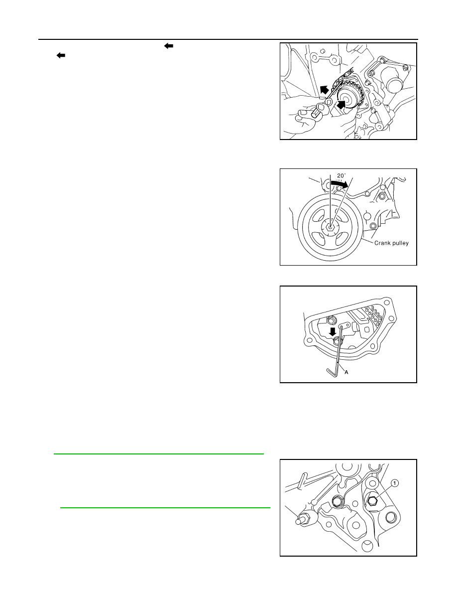
3. Hold timing chain to the side (

) and install the water pump

(

).

CAUTION:

Do not allow cylinder block to interfere with the O-rings

when installing the water pump. 

• Check that timing chain and water pump sprocket are

engaged.

• Tighten water pump bolts alternately and evenly to specifica-

tion.

4. Remove dust and foreign material completely from installation area of timing chain tensioner and rear tim-

ing chain case.

5. Turn the crankshaft pulley approximately 20

° clockwise so that

the timing chain on the timing chain tensioner side is loose.

6. Apply engine oil to the oil feed hole and timing chain tensioner and install the timing chain tensioner.
7. Remove the stopper pin (A).

8. Install intake valve timing control solenoid valve cover (RH) (bank 1) and water pump cover.
a. Before installing, remove all traces of liquid gasket from mating surface of water pump cover and intake

valve timing control solenoid valve cover (RH) (bank 1) using a scraper.

Also remove traces of liquid gasket from the mating surface of the front cover.

b. Apply a continuous bead of liquid gasket to mating surface of intake valve timing control solenoid valve

cover (RH) (bank 1) and water pump cover. Use Genuine RTV Silicone Sealant or equivalent. Refer to

GI-21, "Recommended Chemical Products and Sealants"

.

9. Install cylinder block front drain plug (1) on water pump side of

cylinder block.

• Apply liquid gasket to the threads of cylinder block front drain

plug. 

Use Genuine RTV Silicone Sealant or equivalent. Refer to

GI-21, "Recommended Chemical Products and Sealants"

.

10. Installation of remaining components is in the reverse order of removal.

SLC031B

PBIC0848E

AWBIA0905ZZ

Cylinder block front 
drain plug 

: 9.8 N·m (1.0 kg-m, 87 in-lb)

AWBIA0902ZZ

WATER PUMP

CO-21

< REMOVAL AND INSTALLATION >

[VQ35DE]

C

D

E

F

G

H

I

J

K

L

M

A

CO

N

P

O

• After installation refill engine coolant and check for leaks. Refer to 

CO-11, "Changing Engine Coolant"

and 

CO-10, "System Inspection"

.

CAUTION:

Do not spill coolant in engine compartment. Use a shop cloth to absorb coolant.

• After starting engine, let idle for three minutes, then rev engine up to 3,000 rpm under no load to purge

air from the high-pressure chamber of the chain tensioner. The engine may produce a rattling noise.

This indicates that air still remains in the chamber and is not a matter of concern.

CO-22

< REMOVAL AND INSTALLATION >

[VQ35DE]

THERMOSTAT AND THERMOSTAT HOUSING

THERMOSTAT AND THERMOSTAT HOUSING

Removal and Installation

INFOID:0000000009469271

WARNING:

Do not remove the radiator cap when the engine is hot. Serious burns could occur from high pressure

engine coolant escaping from the radiator. Wrap a thick cloth around the radiator cap. Slowly turn it a

quarter of a turn to release built-up pressure. Carefully remove radiator cap by turning it all the way.

CAUTION:

Perform when engine is cool.

NOTE:

When removing components such as hoses, tubes/lines, etc., cap or plug openings to prevent fluid from spill-

ing.

REMOVAL

1. Drain coolant from radiator. Refer to 

CO-11, "Changing Engine Coolant"

.

2. Disconnect reservoir hose and remove reservoir tank. 
3. Disconnect the harness connector from the VTC solenoid (LH).
4. Disconnect lower radiator hose from thermostat assembly.
5. Remove thermostat assembly (water inlet).

CAUTION:

Do not disassemble thermostat assembly (water inlet).

Replace them as a unit, if necessary.

INSPECTION AFTER REMOVAL

1.

Gasket

2.

Thermostat assembly (water inlet)

AWBIA0847GB

SLC962AA

THERMOSTAT AND THERMOSTAT HOUSING

CO-23

< REMOVAL AND INSTALLATION >

[VQ35DE]

C

D

E

F

G

H

I

J

K

L

M

A

CO

N

P

O

• Place a thread so that it is caught in the valves of the thermostat.

Immerse fully in a container filled with water. Heat while stirring. 

• The valve opening temperature is the temperature at which the

valve opens and the thermostat falls from the thread.

• Continue heating. Check the full-open lift amount.

NOTE:

The full-open lift amount standard temperature for the thermostat is

the reference value.

• After checking the full-open lift amount, lower the water tempera-

ture and check the valve closing temperature. 

• If valve seating at measured values are out of standard range, replace water inlet and thermostat assembly.

INSTALLATION

Installation is in the reverse order of removal.

• Install thermostat with jiggle valve facing upward.

• After installation refill engine coolant and check for leaks. Refer to

CO-11, "Changing Engine Coolant"

 and 

CO-10, "System Inspec-

tion"

.

CAUTION:

Do not spill coolant in engine compartment. Use a shop cloth

to absorb coolant.

SLC949A

Thermostat

Standard Values

Valve opening temperature

Refer to 

CO-27, "Thermostat"

.

Full-open lift amount

Refer to 

CO-27, "Thermostat"

.

Valve closing temperature

Refer to 

CO-27, "Thermostat"

.

SLC948A


Content   ..  300  301  302  303   ..