Nissan Maxima. Manual - part 281


  Index      Nissan     Nissan Maxima (2009-2014 year) - Service and Repair Manual


Search            


Content   ..  279  280  281  282   ..


Nissan Maxima. Manual - part 281


BRM-36

< REMOVAL AND INSTALLATION >

REPLACEMENT OPERATIONS

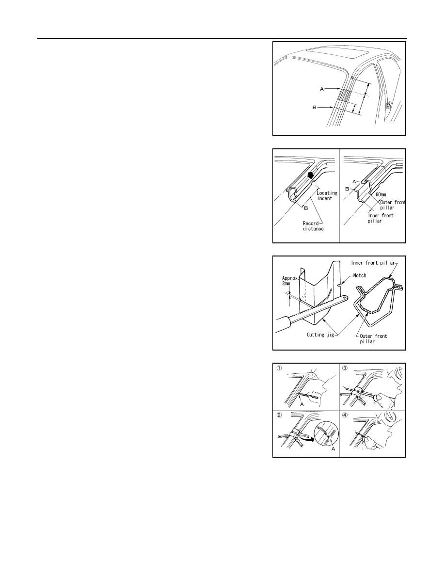
• Front pillar butt joint can be determined anywhere within shaded

area as shown in the figure. The best location for the butt joint is at

position A due to the construction of the vehicle. Refer to the front

pillar section.

• Determine cutting position and record distance from the locating

indent. Use this distance when cutting the service part. Cut outer

front pillar over 60 mm above inner front pillar cut position.

• Prepare a cutting jig to make outer pillar easier to cut. Also, this will

permit service part to be accurately cut at joint position.

• An example of cutting operation using a cutting jig is as follows.

1. Mark cutting lines.

A: Cut position of outer pillar

B: Cut position of inner pillar

2. Align cutting line with notch on jig. Clamp jig to pillar.

3. Cut outer pillar along groove of jig. (At position A)

4. Remove jig and cut remaining portions.

5. Cut inner pillar at position B in same manner.

FOAM REPAIR

During factory assembly, foam insulators are installed in certain body panels and locations around the vehicle.

Use the following procedure(s) to replace any factory-installed foam insulators.

Urethane Foam Applications

Use commercially available spray for sealant (foam material) repair of material used on vehicle. Read instruc-

tions on product for fill procedures.

Fill Procedures

1.  Fill procedures after installation service part.

• Remove foam material remaining on vehicle side.

PIIA0150E

PIIA0151E

PIIA0152E

PIIA0153E

REPLACEMENT OPERATIONS

BRM-37

< REMOVAL AND INSTALLATION >

C

D

E

F

G

H

I

J

L

M

A

B

BRM

N

O

P

• Clean area in which foam was removed.

• Install service part.

• Insert nozzle into hole near fill area and fill foam material or fill in enough to close gap with service part. 

2. Fill procedures before installation service part 
• Remove foam material remaining on vehicle side.

• Clean area in which foam material on wheelhouse outer side was removed.

NOTE:

Fill in enough to close gap with service part while avoiding flange

area.

• Install service part.

NOTE:

Refer to label for information on working times.

LIIA1081E

LIIA1082E

BRM-38

< REMOVAL AND INSTALLATION >

REPLACEMENT OPERATIONS

Note:
Views F & G are shown with the body side outer removed.

1.

Body side outer 

2.

Body side insulation (foam) upper 
front pillar

3.

Body side insulation (foam) front pil-
lar

4.

Roof panel assembly

5.

Roof panel insulation (foam) front 
roof rail (standard roof)

6.

Body side insulation (foam) rear pil-
lar

7.

Body side insulation (foam) lower 
rear pillar

8.

Body side insulation strip front pillar 
lower reinforcement

9.

Body side insulation strip, center pil-
lar reinforcement

AWKIA1361GB

REPLACEMENT OPERATIONS

BRM-39

< REMOVAL AND INSTALLATION >

C

D

E

F

G

H

I

J

L

M

A

B

BRM

N

O

P

Hoodledge

INFOID:0000000009465847

Replacement parts

z

Front suspension spring support

z

Hoodledge reinforcement

z

Hoodledge lower assembly

z

Upper radiator core support

AWKIA1363GB


Content   ..  279  280  281  282   ..