Nissan Maxima. Manual - part 232


  Index      Nissan     Nissan Maxima (2009-2014 year) - Service and Repair Manual


Search            


Content   ..  230  231  232  233   ..


Nissan Maxima. Manual - part 232


BCS

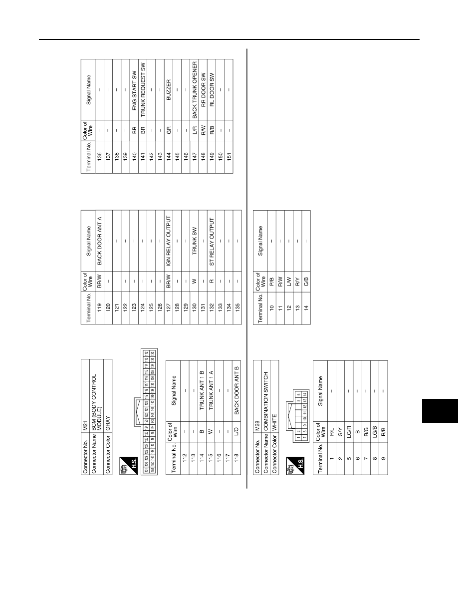
BCM (BODY CONTROL MODULE)

BCS-75

< WIRING DIAGRAM >

[BCM]

C

D

E

F

G

H

I

J

K

L

B

A

O

P

N

ABMIA3926GB

BCS-76

< SYMPTOM DIAGNOSIS >

[BCM]

COMBINATION SWITCH SYSTEM SYMPTOMS

SYMPTOM DIAGNOSIS

COMBINATION SWITCH SYSTEM SYMPTOMS

Symptom Table

INFOID:0000000009467081

1. Perform the data monitor of CONSULT to check for any malfunctioning item.
2. Check the malfunction combinations.

Malfunction item: 

×

3. Identify the malfunctioning part from the agreed combination and repair or replace the part.

Malfunction combi-

nation

Data monitor item

FR WI

PER HI

FR WIP

ER LOW

F

R

 W

A

SH

ER

 S

W

FR WI

PER INT

INT VOL

U

ME

TURN SIG

NAL R

TURN SIGNAL L

TA

IL

 LA

MP 

SW

H

I BEAM SW

HEAD LAMP SW 

1

HEAD LAMP SW 

2

P

ASSI

N

G

 SW

AU

T

O

 LI

GH

T

 S

W

FR F

O

SW

A

×

×

×

×

B

×

×

×

×

C

×

×

×

D

×

×

×

E

×

×

F

×

×

G

×

×

H

×

×

×

I

×

×

×

×

J

×

×

×

×

K

All  Items

L

If only one item is detected or the item is not applicable to the combinations A to J 

Malfunction 

combination

Malfunctioning part

Repair or replace

A

Combination switch INPUT 1 circuit

Inspect the combination switch input circuit applicable to the malfunctioning 
part. Refer to 

BCS-37, "Diagnosis Procedure"

.

B

Combination switch INPUT 2 circuit

C

Combination switch INPUT 3 circuit

D

Combination switch INPUT 4 circuit

E

Combination switch INPUT 5 circuit

F

Combination switch OUTPUT 1 circuit

Inspect the combination switch output circuit applicable to the malfunction-
ing part. Refer to 

BCS-39, "Diagnosis Procedure"

.

G

Combination switch OUTPUT 2 circuit

H

Combination switch OUTPUT 3 circuit

I

Combination switch OUTPUT 4 circuit

J

Combination switch OUTPUT 5 circuit

K

BCM

Replace BCM. Refer to 

BCS-79, "Removal and Installation"

.

L

Combination switch

Replace the combination switch. Refer to 

WW-85, "Removal and Installa-

tion"

.

BCS

PRECAUTIONS

BCS-77

< PRECAUTION >

[BCM]

C

D

E

F

G

H

I

J

K

L

B

A

O

P

N

PRECAUTION

PRECAUTIONS

Precaution for Supplemental Restraint System (SRS) "AIR BAG" and "SEAT BELT 
PRE-TENSIONER"

INFOID:0000000009467082

The Supplemental Restraint System such as “AIR BAG” and “SEAT BELT PRE-TENSIONER”, used along

with a front seat belt, helps to reduce the risk or severity of injury to the driver and front passenger for certain

types of collision. This system includes seat belt switch inputs and dual stage front air bag modules. The SRS

system uses the seat belt switches to determine the front air bag deployment, and may only deploy one front

air bag, depending on the severity of a collision and whether the front occupants are belted or unbelted.

Information necessary to service the system safely is included in the SR and SB section of this Service Man-

ual.

WARNING:

• To avoid rendering the SRS inoperative, which could increase the risk of personal injury or death in

the event of a collision which would result in air bag inflation, all maintenance must be performed by

an authorized NISSAN/INFINITI dealer.

• Improper maintenance, including incorrect removal and installation of the SRS, can lead to personal

injury caused by unintentional activation of the system. For removal of Spiral Cable and Air Bag

Module, see the SR section.

• Do not use electrical test equipment on any circuit related to the SRS unless instructed to in this

Service Manual. SRS wiring harnesses can be identified by yellow and/or orange harnesses or har-

ness connectors.

PRECAUTIONS WHEN USING POWER TOOLS (AIR OR ELECTRIC) AND HAMMERS

WARNING:

• When working near the Airbag Diagnosis Sensor Unit or other Airbag System sensors with the Igni-

tion ON or engine running, DO NOT use air or electric power tools or strike near the sensor(s) with a

hammer. Heavy vibration could activate the sensor(s) and deploy the air bag(s), possibly causing

serious injury.

• When using air or electric power tools or hammers, always switch the Ignition OFF, disconnect the

battery, and wait at least 3 minutes before performing any service.

BCS-78

< PREPARATION >

[BCM]

PREPARATION

PREPARATION

PREPARATION

Commercial Service Tools

INFOID:0000000009467083

Tool name

Description

Power tool

Loosening nuts, screws and bolts

One-way screw removal tool

Removing one-way screws

PIIB1407E

ALMIA0486ZZ


Content   ..  230  231  232  233   ..