Nissan Maxima. Manual - part 195


  Index      Nissan     Nissan Maxima (2009-2014 year) - Service and Repair Manual


Search            


Content   ..  193  194  195  196   ..


Nissan Maxima. Manual - part 195


AV-600

< DTC/CIRCUIT DIAGNOSIS >

[COLOR DISPLAY - W/BOSE & NAVI]

STEERING SWITCH

STEERING SWITCH

Description

INFOID:0000000009471516

When one of the steering wheel audio control switches is pushed, the resistance in the steering wheel audio

control switch circuit changes, depending on which button is pushed.

Diagnosis Procedure

INFOID:0000000009471517

Regarding Wiring Diagram information, refer to 

AV-614, "Wiring Diagram - With BOSE audio system With Nav-

igation System"

.

1.

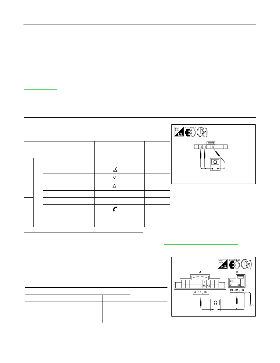
CHECK STEERING WHEEL AUDIO CONTROL SWITCH RESISTANCE

1. Turn ignition switch OFF.

2. Disconnect steering wheel audio control switch connector M88.

3. Check resistance between steering switch connector terminals.

Do the steering wheel audio control switches check OK?

YES

>> GO TO 2.

NO

>> Replace steering wheel audio control switch. Refer to 

AV-667, "Removal and Installation"

.

2.

CHECK HARNESS BETWEEN COMBINATION SWITCH (SPIRAL CABLE) AND AV CONTROL UNIT

1. Disconnect AV control unit connector M160 and combination

switch (spiral cable) connector M30.

2. Check continuity between AV control unit harness connector

M160 (A) and combination switch (spiral cable) harness connec-

tor M30 (B).

3. Check continuity between AV switch connector M160 (A) and ground.

Terminal

Signal name

Condition

Resistance 

(

Ω)

(Approx.)

14

17

Enter

Depress ENTER switch.

2023

Voice recognition

Depress  

switch.

723

Menu (down)

Depress  

switch.

321

Menu (up)

Depress  

switch.

121

Source

Depress SOURCE switch.

0

15

Menu back

Depress the back switch. 

723

Phone

Depress  

switch. 

321

Volume (up)

Depress VOL up switch.

121

Volume (down)

Depress VOL down switch.

0

AWNIA1708ZZ

A

Continuity

Connector

Terminal

Connector

Terminal

M160

6

M30

24

Yes

15

33

16

31

AWNIA1709ZZ

AV

STEERING SWITCH

AV-601

< DTC/CIRCUIT DIAGNOSIS >

[COLOR DISPLAY - W/BOSE & NAVI]

C

D

E

F

G

H

I

J

K

L

M

B

A

O

P

Are the continuity results as specified?

YES

>> GO TO 3.

NO

>> Repair harness.

3.

COMBINATION SWITCH (SPIRAL CABLE) CHECK

1. Disconnect combination switch (spiral cable) connector M88.

2. Check continuity between combination switch (spiral cable) har-

ness connector M30 (A) and M88 (B).

Does the combination switch (spiral cable) check OK?

YES

>> Inspection End.

NO

>> Replace combination switch (spiral cable). Refer to 

SR-15, "Removal and Installation"

.

A

Continuity

Connector

Terminal

M160

6

Ground

No

15

16

A

B

Continuity

Connector

Terminal

Connector

Terminal

M30

24

M88

14

Yes

31

15

33

17

AWNIA1710ZZ

AV-602

< ECU DIAGNOSIS INFORMATION >

[COLOR DISPLAY - W/BOSE & NAVI]

AV CONTROL UNIT

ECU DIAGNOSIS INFORMATION

AV CONTROL UNIT

Reference Value

INFOID:0000000009471518

VALUES ON THE DIAGNOSIS TOOL

CONSULT data monitor item

TERMINAL LAYOUT

PHYSICAL VALUES

Display Item

Dis-
play

Vehicle status

Remarks

VHCL SPD SIG

ON

Vehicle speed >0 km/h (0 MPH)

Changes in indication may be delayed. This is 
normal.

OFF

Vehicle speed =0 km/h (0 MPH)

PKB SIG

ON

Parking brake is applied.

Changes in indication may be delayed. This is 
normal.

OFF

Parking brake is released.

ILLUM SIG

ON

Block the light beam from the auto 
light optical sensor when the light 
SW is ON.

OFF

Expose the auto light optical sensor 
to light when the light SW is OFF or 
ON.

IGN SIG

ON

Ignition switch ON

OFF

Ignition switch in ACC position

REV SIG

ON

Selector lever in R position

Changes in indication may be delayed. This is 
normal.

OFF

Selector lever in any position other 
than R

AWNIA1934ZZ

AV

AV CONTROL UNIT

AV-603

< ECU DIAGNOSIS INFORMATION >

[COLOR DISPLAY - W/BOSE & NAVI]

C

D

E

F

G

H

I

J

K

L

M

B

A

O

P

Terminal

(Wire color)

Description

Condition

Reference value

(Approx.)

+

Signal name

Input/

Output

1

(B/P)

Ground Amp. ON signal

Output

Ignition 

switch 

ON

Battery voltage

2

(G)

3

(R)

Pre-amp. audio signal front 
LH

Output

Ignition 

switch 

ON

Audio output

4

(W/R)

5

(W/L)

Pre-amp. audio signal rear 
LH

Output

Ignition 

switch 

ON

Audio output

6

(W/G)

15

(L/B)

Steering switch signal A

Input

Ignition 

switch 

OFF

Depress SOURCE switch.

0V

Depress    switch.

1.0V

Depress    switch.

2.0V

Depress  


switch.

3.0V

Depress ENTER switch.

4.0V

Except for above.

5.0V

7

(V/Y)

Ground ACC power supply

Input

Ignition 

switch 

ACC

Battery voltage

9

(R/L)

Ground Illumination signal

Input

OFF

Lighting switch is OFF

0V

Lighting switch is ON

Battery voltage

11

(B)

12

(W)

Pre-amp. audio signal front 
RH

Output

Ignition 

switch 

ON

Audio output

13

(V)

14

(LG)

Audio signal rear RH

Output

Ignition 

switch 

ON

Audio output

15

(L/B)

Ground

Steering switch signal 
ground

Ignition 

switch 

ON

0V

SKIB3609E

SKIB3609E

SKIB3609E

SKIB3609E


Content   ..  193  194  195  196   ..