Nissan Maxima. Manual - part 165
AV-480
< PREPARATION >
[COLOR DISPLAY - W/ BOSE]
PREPARATION
PREPARATION
PREPARATION
Special Service Tool
INFOID:0000000009471395
The actual shape of the tools may differ from those illustrated here.
Commercial Service Tools
INFOID:0000000009471396
Tool number
(TechMate No.)
Tool name
Description
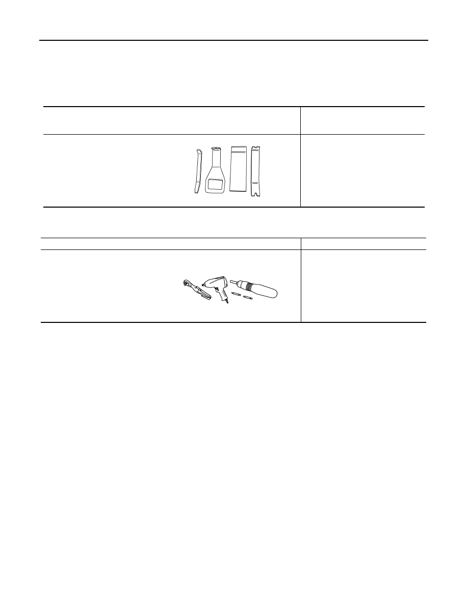
—
(J-46534)
Trim Tool Set
Removing trim components
AWJIA0483ZZ
Tool name
Description
Power tool
Loosening nuts, screws and bolts
PIIB1407E