Nissan Maxima. Manual - part 1223


  Index      Nissan     Nissan Maxima (2009-2014 year) - Service and Repair Manual


Search            


Content   ..  1221  1222  1223  1224   ..


Nissan Maxima. Manual - part 1223


WW-16

< SYSTEM DESCRIPTION >

DIAGNOSIS SYSTEM (IPDM E/R)
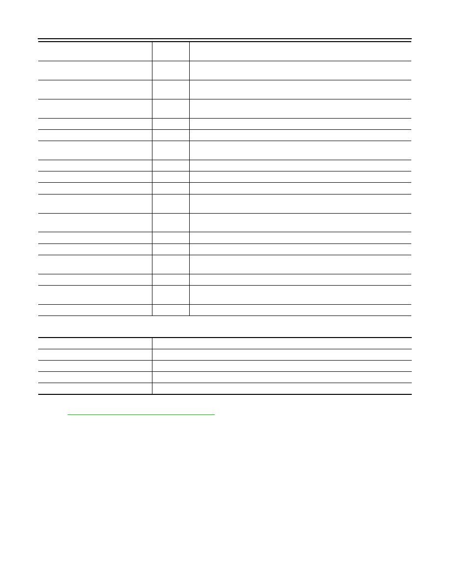
ACTIVE TEST

CAN DIAG SUPPORT MNTR

Refer to 

LAN-12, "CAN Diagnostic Support Monitor"

.

HL HI REQ [On/Off]

×

Indicates high beam request signal received from BCM on CAN communication 
line

FR FOG REQ [On/Off]

×

Indicates front fog light request signal received from BCM on CAN communica-
tion line

FR WIP REQ [Stop/1LOW/Low/Hi]

×

Indicates front wiper request signal received from BCM on CAN communication 
line

WIP AUTO STOP [STOP P/ACT P]

×

Indicates condition of front wiper auto stop signal

WIP PROT [Off/BLOCK]

×

Indicates condition of front wiper fail-safe operation

IGN RLY1 -REQ [On/Off]

Indicates ignition switch ON signal received from BCM on CAN communication 
line

IGN RLY [On/Off]

×

Indicates condition of ignition relay-1

PUSH SW [On/Off]

Indicates condition of push-button ignition switch

INTER/NP SW [On/Off]

Indicates condition of CVT shift position

ST RLY CONT [On/Off]

Indicates starter relay status signal received from BCM on CAN communication 
line

IHBT RLY -REQ [On/Off]

Indicates starter control relay signal received from BCM on CAN communication 
line

ST/INHI RLY [Off/ ST /INHI]

Indicates condition of starter relay and starter control relay

DETENT SW [On/Off]

Indicates condition of CVT shift selector (park position switch)

DTRL REQ [Off]

Indicates daytime light request signal received from BCM on CAN communica-
tion line

OIL P SW [Open/Close]

Indicates condition of oil pressure switch

THFT HRN REQ [On/Off]

Indicates theft warning horn request signal received from BCM on CAN commu-
nication line

HORN CHIRP [On/Off]

Indicates horn reminder signal received from BCM on CAN communication line

Monitor Item [Unit]

Main

Signals

Description

Test item

Description

HORN

This test is able to check horn operation [On].

FRONT WIPER

This test is able to check wiper motor operation [Hi/Lo/Off].

MOTOR FAN

This test is able to check cooling fan operation [4/3/2/1].

EXTERNAL LAMPS

This test is able to check external lamp operation [Fog/Hi/Lo/Tail/Off].

WIPER AND WASHER FUSE

WW-17

< DTC/CIRCUIT DIAGNOSIS >

C

D

E

F

G

H

I

J

K

M

A

B

WW

N

O

P

DTC/CIRCUIT DIAGNOSIS

WIPER AND WASHER FUSE

Description

INFOID:0000000010048948

Fuse list

Diagnosis Procedure

INFOID:0000000010048949

1.

 CHECK FUSES

Check that the following fuses are not blown.

Is the fuse blown?

YES

>> Replace the blown fuse after repairing the affected circuit.

NO

>> The fuse is normal.

Unit

Location

Fuse No.

Capacity

Front wiper motor

IPDM E/R

55

30 A

Front washer motor

IPDM E/R

38

10 A

Unit

Location

Fuse No.

Capacity

Front wiper motor

IPDM E/R

55

30 A

Front washer motor

IPDM E/R

38

10 A

WW-18

< DTC/CIRCUIT DIAGNOSIS >

FRONT WIPER MOTOR LO CIRCUIT

FRONT WIPER MOTOR LO CIRCUIT

Component Function Check

INFOID:0000000010048950

1.

 CHECK FRONT WIPER LO OPERATION

IPDM E/R AUTO ACTIVE TEST

1. Start IPDM E/R auto active test. Refer to 

PCS-11, "Diagnosis Description"

.

2. Check that the front wiper operates at the LO operation.

CONSULT ACTIVE TEST

1. Select "FRONT WIPER" of IPDM E/R active test item.

2. While operating the test item, check front wiper LO operation and OFF.

Does the front wiper operate?

YES

>> Front wiper motor LO circuit is normal.

NO

>> Refer to 

WW-18, "Diagnosis Procedure"

.

Diagnosis Procedure

INFOID:0000000010048951

Regarding Wiring Diagram information, refer to 

WW-63, "Wiring Diagram"

.

1.

 CHECK FRONT WIPER MOTOR (LO) OUTPUT VOLTAGE

CONSULT ACTIVE TEST

1. Turn the ignition switch OFF.

2. Disconnect front wiper motor.

3. Turn the ignition switch ON.

4. Select "FRONT WIPER" of IPDM E/R active test item.

5. While operating the test item, check voltage between IPDM E/R

harness connector and ground.

Is the measurement normal?

YES

>> GO TO 2

NO

>> Replace IPDM E/R. Refer to 

PCS-35, "Removal and Installation"

.

2.

 CHECK FRONT WIPER MOTOR (LO) OPEN CIRCUIT

LO

: Front wiper LO operation

OFF

: Stop the front wiper.

Terminals

Test item

Voltage (V) (Ap-

prox.)

(+)

(-)

IPDM E/R

Ground

FRONT WIPER

Connector

Terminal

E18

4

LO

Battery voltage

OFF

0V

ALLIA0922ZZ

FRONT WIPER MOTOR LO CIRCUIT

WW-19

< DTC/CIRCUIT DIAGNOSIS >

C

D

E

F

G

H

I

J

K

M

A

B

WW

N

O

P

1. Turn the ignition switch OFF.

2. Disconnect IPDM E/R.

3. Check continuity between IPDM E/R harness connector (A) and

front wiper motor harness connector (B).

Does continuity exist?

YES

>> Replace front wiper motor. Refer to 

WW-78, "FRONT

WIPER DRIVE ASSEMBLY : Removal and Installation"

.

NO

>> Repair or replace harness.

IPDM E/R

Front wiper motor

Continuity

Connector

Terminal

Connector

Terminal

E18 (A)

4

E25 (B)

1

Yes

ALLIA0816ZZ


Content   ..  1221  1222  1223  1224   ..