Nissan Maxima. Manual - part 1217


  Index      Nissan     Nissan Maxima (2009-2014 year) - Service and Repair Manual


Search            


Content   ..  1215  1216  1217  1218   ..


Nissan Maxima. Manual - part 1217


PREPARATION

WT-57

< PREPARATION >

C

D

F

G

H

I

J

K

L

M

A

B

WT

N

O

P

PREPARATION

PREPARATION

Special Service Tool

INFOID:0000000009466850

The actual shape of the tools may differ from those illustrated here.

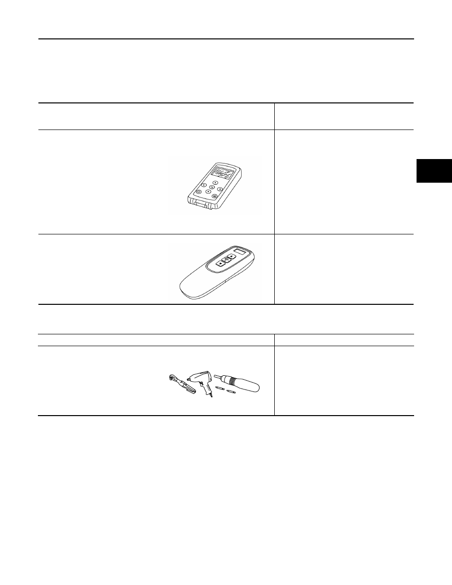
Commercial Service Tools

INFOID:0000000009466851

Tool number 
(TechMate No.)
Tool name

Description

(J-50190)
Signal Tech II

• Activate and display TPMS transmitter IDs
• Display tire pressure reported by the TPMS 

transmitter

• Read TPMS DTCs
• Register TPMS transmitter IDs
• Test remote keyless entry keyfob relative 

signal strength

• Check Intelligent Key relative signal 

strength

• Confirm vehicle Intelligent Key antenna sig-

nal strength

• Compatible with future sensors
• Equipped with a display

KV48105501
(J-45295-A)
Transmitter activation tool

• Activate TPMS transmitter IDs
• Compatible with future sensors
• Equipped with a display (KV48105501 only)

ALEIA0131ZZ

ALEIA0183ZZ

Tool name

Description

Power tool

Loosening nuts, screws and bolts

PIIB1407E

WT-58

< PERIODIC MAINTENANCE >

ROAD WHEEL

PERIODIC MAINTENANCE

ROAD WHEEL

Inspection

INFOID:0000000009466852

ALUMINUM WHEEL

1. Check tires for wear and improper inflation.
2. Check wheels for deformation, cracks and other damage. If deformed, remove wheel and check wheel

runout.

a. Remove tire from aluminum wheel and mount on a tire balance machine. Refer to 

WT-62, "Removal and

Installation"

 to remove transmitter.

b. Set dial indicator as shown and rotate the wheel to check for

runout.

• Replace wheel if runout exceeds specification.

Wheel runout

Refer to 

WT-65

.

SFA975B

TIRE PRESSURE RECEIVER

WT-59

< REMOVAL AND INSTALLATION >

C

D

F

G

H

I

J

K

L

M

A

B

WT

N

O

P

REMOVAL AND INSTALLATION

TIRE PRESSURE RECEIVER

Removal and Installation

INFOID:0000000009466853

REMOVAL

1. Remove instrument lower panel LH. Refer to 

IP-11, "Removal and Installation"

.

2. Locate tire pressure receiver (1) to the right of the steering col-

umn and disconnect the harness connector from the tire pres-

sure receiver.

3. Remove tire pressure receiver (1) from bracket using a suitable

tool to release the bracket.

INSTALLATION

Installation is in the reverse order of removal.

AWEIA0123ZZ

WT-60

< REMOVAL AND INSTALLATION >

ROAD WHEEL TIRE ASSEMBLY

ROAD WHEEL TIRE ASSEMBLY

Adjustment

INFOID:0000000009466854

BALANCING WHEELS (ADHESIVE WEIGHT TYPE)

Preparation Before Adjustment

Remove inner and outer balance weights from the road wheel. Using releasing agent, remove double-faced

adhesive tape from the road wheel.

CAUTION:

• Be careful not to scratch the road wheel during removal.

• After removing double-faced adhesive tape, wipe clean all traces of releasing agent from the road

wheel.

Wheel Balance Adjustment

• If a balancer machine has an adhesive weight mode setting, select the adhesive weight mode setting and

skip Step 2. below. If a balancer machine only has the clip-on (rim flange) weight mode setting, follow Step 2.

to calculate the correct size adhesive weight.

1. Set road wheel on balancer machine using the center hole as a guide. Start the balancer machine.
2. For balancer machines that only have a clip-on (rim flange) weight mode setting, follow this step to calcu-

late the correct size adhesive weight to use. When inner and outer imbalance values are shown on the

balancer machine indicator, multiply outer imbalance value by 5/3 (1.67) to determine balance weight that

should be used. Select the outer balance weight with a value closest to the calculated value above and

install in to the designated outer position of, or at the designated angle in relation to the road wheel.

a. Indicated imbalance value 

× 5/3 = balance weight to be installed

Calculation example:

23 g (0.81 oz) 

× 5/3 (1.67) = 38.33 g (1.35 oz) ⇒ 40 g (1.41 oz)

balance weight (closer to calculated balance weight value)

NOTE:

Note that balance weight value must be closer to the calculated

balance weight value.

Example:

37.4 

⇒ 35 g (1.23 oz)

37.5 

⇒ 40 g (1.41 oz)

3. Install balance weight in the position shown.

CAUTION:

• Do not install the inner balance weight before installing

the outer balance weight.

• Before installing the balance weight, be sure to clean the

mating surface of the road wheel.

• When installing balance weight (1) to road wheel, set it into the

grooved area (A) on the inner wall of the road wheel as shown

so that the balance weight center (B) is aligned with the bal-

ancer machine indication position (angle) (C).

CAUTION:

• Always use Genuine NISSAN adhesive balance weights.

• Balance weights are non-reusable; always replace with

new ones.

• Do not install more than three sheets of balance weight.

SMA054D

JPEIC0040ZZ


Content   ..  1215  1216  1217  1218   ..