Nissan Maxima. Manual - part 1213


  Index      Nissan     Nissan Maxima (2009-2014 year) - Service and Repair Manual


Search            


Content   ..  1211  1212  1213  1214   ..


Nissan Maxima. Manual - part 1213


BCM (BODY CONTROL MODULE)

WT-41

< ECU DIAGNOSIS INFORMATION >

C

D

F

G

H

I

J

K

L

M

A

B

WT

N

O

P

103

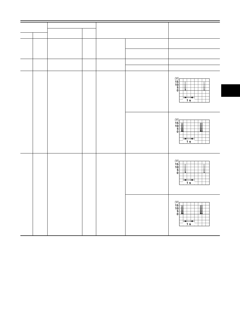
(V)

Ground Trunk lid opening.

Output Trunk lid

Open (trunk lid opener ac-
tuator is activated)

Battery voltage

Close (trunk lid opener ac-
tuator is not activated)

0V

110

(V/W)

Ground Trunk room lamp

Output Trunk room lamp

ON

0V

OFF

Battery voltage

114

(B)

Ground

Trunk room antenna 
1 (-)

Output

Ignition switch 
OFF

When Intelligent Key is in 
the passenger compart-
ment

When Intelligent Key is not 
in the passenger compart-
ment

115
(W)

Ground

Trunk room antenna 
1 (+)

Output

Ignition switch 
OFF

When Intelligent Key is in 
the passenger compart-
ment

When Intelligent Key is not 
in the passenger compart-
ment

Terminal No.

(Wire color)

Description

Condition

Value

(Approx.)

Signal name

Input/ 

Output

(+)

(-)

JMKIA0062GB

JMKIA0063GB

JMKIA0062GB

JMKIA0063GB

WT-42

< ECU DIAGNOSIS INFORMATION >

BCM (BODY CONTROL MODULE)

118

(L/O)

Ground

Rear bumper anten-
na (-)

Output

When the trunk 
lid request switch 
is operated with 
ignition switch 
OFF

When Intelligent Key is in 
the antenna detection area

When Intelligent Key is not 
in the antenna detection 
area

119

(BR/

W)

Ground

Rear bumper anten-
na (+)

Output

When the trunk 
lid request switch 
is operated with 
ignition switch 
OFF

When Intelligent Key is in 
the antenna detection area

When Intelligent Key is not 
in the antenna detection 
area

127

(BR/

W)

Ground

Ignition relay (IPDM 
E/R) control

Output Ignition switch

OFF or ACC

Battery voltage

ON

0V

130
(W)

Ground

Trunk room lamp 
switch

Input

Trunk room lamp 
switch

OFF (trunk is closed)

11.8V

ON (trunk is open)

0V

132

(R)

Ground

Starter motor relay 
control

Output

Ignition switch 
ON

When selector lever is in P 
or N position and the brake 
is depressed

Battery voltage

When selector lever is in P 
or N position and the brake 
is not depressed

0V

Terminal No.

(Wire color)

Description

Condition

Value

(Approx.)

Signal name

Input/ 

Output

(+)

(-)

JMKIA0062GB

JMKIA0063GB

JMKIA0062GB

JMKIA0063GB

JPMIA0011GB

BCM (BODY CONTROL MODULE)

WT-43

< ECU DIAGNOSIS INFORMATION >

C

D

F

G

H

I

J

K

L

M

A

B

WT

N

O

P

Self-Diagnosis (With CONSULT)

INFOID:0000000010046359

NOTE:

The Signal Tech II Tool (J-50190) can be used to perform the following functions. Refer to the Signal Tech II

User Guide for additional information.

• Activate and display TPMS transmitter IDs

• Display tire pressure reported by the TPMS transmitter

• Read TPMS DTCs

• Register TPMS transmitter IDs

FUNCTION

Self-Diagnostic Results Mode

140

(BR)

Ground

Engine switch (push 
switch)

Input

Engine switch 
(push switch)

Pressed

0V

Not pressed

Battery voltage

141

(BR)

Ground

Trunk opener request 
switch

Input

Trunk opener re-
quest switch

ON (pressed)

0V

OFF (not pressed)

1.0V

144

(GR)

Ground

Request switch buzz-
er

Output

Request switch 
buzzer

Sounding

0V

Not sounding

Battery voltage

147

(L/R)

Ground

Trunk lid opener 
switch

Input

Trunk lid opener 
switch

Pressed

0V

Not pressed

Battery voltage

148

(R/W)

Ground Rear door RH switch

Input

Rear door RH 
switch

OFF (when rear door RH 
closes)

11.8V

ON (when rear door RH 
opens)

0V

149

(R/B)

Ground Rear door LH switch

Input

Rear door LH 
switch

OFF (when rear door LH 
closes)

11.8V

ON (when rear door LH 
opens)

0V

Terminal No.

(Wire color)

Description

Condition

Value

(Approx.)

Signal name

Input/ 

Output

(+)

(-)

JPMIA0016GB

JPMIA0011GB

JPMIA0011GB

WT-44

< ECU DIAGNOSIS INFORMATION >

BCM (BODY CONTROL MODULE)

NOTE:
Before performing the self-diagnosis, be sure to register the ID or else the actual malfunction location may be different from that dis-
played on CONSULT.

Self-Diagnosis (Without CONSULT)

INFOID:0000000010046360

NOTE:

The Signal Tech II Tool (J-50190) can be used to perform the following functions. Refer to the Signal Tech II

User Guide for additional information.

• Activate and display TPMS transmitter IDs

• Display tire pressure reported by the TPMS transmitter

• Read TPMS DTCs

• Register TPMS transmitter IDs

SELF DIAGNOSTIC PROCEDURE (WITHOUT CONSULT)

1. Turn ignition switch ON.

2. Ground the tire pressure warning check connector to initiate self diagnosis.

3. Compare the flashing pattern with the flash code chart below.

NOTE:

Diagnostic item

Diagnostic item is detected when ···

Reference 

page

LOW - PRESSURE - FL [C1704]
LOW - PRESSURE - FR [C1705]
LOW - PRESSURE - RR [C1706]
LOW - PRESSURE - RL [C1707]

Tire pressures dropped below specified value.  Refer to 

WT-8, 

"System Description"

.

[NO-DATA] - FL [C1708]
[NO-DATA] - FR [C1709]
[NO-DATA] - RR [C1710]
[NO-DATA] - RL [C1711]

Data from FL transmitter cannot be received.
Data from FR transmitter cannot be received.
Data from RR transmitter cannot be received.
Data from RL transmitter cannot be received.

WT-13

[CHECKSUM- ERR] - FL [C1712]
[CHECKSUM- ERR] - FR [C1713]
[CHECKSUM- ERR] - RR [C1714]
[CHECKSUM- ERR] - RL [C1715]

Checksum data from FL transmitter is malfunctioning.
Checksum data from FR transmitter is malfunctioning.
Checksum data from RR transmitter is malfunctioning.
Checksum data from RL transmitter is malfunctioning.

WT-15

[PRESSDATA- ERR] - FL [C1716]
[PRESSDATA- ERR] - FR [C1717]
[PRESSDATA- ERR] - RR [C1718]
[PRESSDATA- ERR] - RL [C1719]

Air pressure data from FL transmitter is malfunctioning.
Air pressure data from FR transmitter is malfunctioning.
Air pressure data from RR transmitter is malfunctioning.
Air pressure data from RL transmitter is malfunctioning.

WT-17

[CODE- ERR] - FL [C1720]
[CODE- ERR] - FR [C1721]
[CODE- ERR] - RR [C1722]
[CODE- ERR] - RL [C1723]

Function code data from FL transmitter is malfunctioning.
Function code data from FR transmitter is malfunctioning.
Function code data from RR transmitter is malfunctioning.
Function code data from RL transmitter is malfunctioning.

WT-15

[BATT - VOLT - LOW] - FL [C1724]
[BATT - VOLT - LOW] - FR [C1725]
[BATT - VOLT - LOW] - RR [C1726]
[BATT - VOLT - LOW] - RL [C1727]

Battery voltage of FL transmitter drops.
Battery voltage of FR transmitter drops.
Battery voltage of RR transmitter drops.
Battery voltage of RL transmitter drops.

WT-15

VHCL_SPEED_SIG_ERR [C1729]

Vehicle speed signal is in error.

WT-19

CONTROL MODULE [C1734]

TPMS malfunction in BCM.

WT-20

ALEIA0050GB


Content   ..  1211  1212  1213  1214   ..