Nissan Maxima. Manual - part 1190


  Index      Nissan     Nissan Maxima (2009-2014 year) - Service and Repair Manual


Search            


Content   ..  1188  1189  1190  1191   ..


Nissan Maxima. Manual - part 1190


WCS-12

< SYSTEM DESCRIPTION >

WARNING CHIME SYSTEM

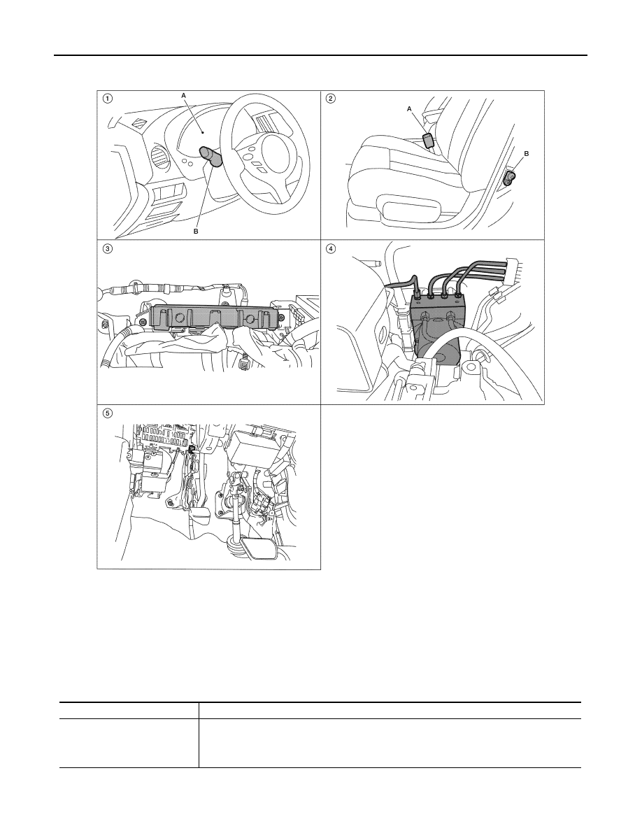
PARKING BRAKE RELEASE WARNING CHIME : Component Parts Location

INFOID:0000000010049228

PARKING BRAKE RELEASE WARNING CHIME : Component Description

INFOID:0000000010049229

ALNIA1155ZZ

1.

A. Combination meter M24
B. Combination switch (lighting and 
turn signal switch) M28

2.

A. Seat belt buckle switch LH B202
B. Front door switch LH B8

3.

BCM M16, M17, M18, M19 (view with 
instrument panel removed)

4.

ABS actuator and electric unit (control 
unit) E26

5.

Parking brake switch E35 [view with 
instrument panel lower cover (LH) re-
moved]

Unit

Description

Combination meter

• Judges whether the parking brake is released using the parking brake switch signal from the 

parking brake switch, and sounds the buzzer if necessary.

• Receives a vehicle speed signal from ABS actuator and electric unit (control unit) via CAN 

communication line.

WCS

WARNING CHIME SYSTEM

WCS-13

< SYSTEM DESCRIPTION >

C

D

E

F

G

H

I

J

K

L

M

B

A

O

P

ABS actuator and electric unit 
(control unit)

Transmits the vehicle speed signal to combination meter via CAN communication line.

Parking brake switch

Transmits parking brake switch signal to the combination meter.

Unit

Description

WCS-14

< SYSTEM DESCRIPTION >

DIAGNOSIS SYSTEM (METER)

DIAGNOSIS SYSTEM (METER)

Diagnosis Description

INFOID:0000000010054751

SELF-DIAGNOSIS MODE

• Odo/trip meter and information display segment operation can be checked in self-diagnosis mode.

• Meters/gauges can be checked in self-diagnosis mode.

OPERATION PROCEDURE

1. Turn the ignition switch OFF.
2. While pushing the odo/trip meter switch, turn the ignition switch ON again.
3. Push the odo/trip meter switch at least 3 times within 7 seconds after the ignition switch is turned ON.
4. The unified meter control unit is turned to self-diagnosis mode.

• All the segments on the odo/trip meter illuminate.

• Dots in all segments of information display LCD (1) flash alter-

nately.

NOTE:

If any of the segments are not displayed, replace the combina-

tion meter. Refer to 

MWI-122, "Removal and Installation"

.

5. Push the odo/trip meter switch. Each meter/gauge should indicate as shown in the figure.

CONSULT Function (METER/M&A)

INFOID:0000000010054752

CONSULT can display each diagnostic item using the diagnostic test modes shown following.

SKIB1206J

JSNIA0020GB

AWNIA2309ZZ

WCS

DIAGNOSIS SYSTEM (METER)

WCS-15

< SYSTEM DESCRIPTION >

C

D

E

F

G

H

I

J

K

L

M

B

A

O

P

SELF-DIAG RESULTS

Display Item List

Refer to 

MWI-51, "DTC Index"

.

DATA MONITOR

Display Item List

X: Applicable

METER/M&A diagnosis mode

Description

SELF DIAGNOSTIC RESULT

Displays combination meter self-diagnosis results.

DATA MONITOR

Displays combination meter input/output data in real time.

CAN DIAG SUPPORT MNTR

The result of transmit/receive diagnosis of CAN communication can be read.

Display item [Unit]

MAIN

SIGNALS

SELECTION 

FROM MENU

Description

SPEED METER [km/h] or [mph]

X

X

Displays the value of vehicle speed signal.

SPEED OUTPUT [km/h] or [mph]

X

X

Displays the value of vehicle speed signal, which is transmitted to 
each unit with CAN communication.

ODO OUTPUT

X

Displays the value, which is calculated by vehicle speed signal.

TACHO METER [rpm]

X

X

Displays the value of engine speed signal, which is input from ECM.

FUEL METER [lit.]

X

X

Displays the value, which processes a resistance signal from fuel 
gauge.

W TEMP METER [

°C] or [°F]

X

X

Displays the value of engine coolant temperature signal, which is in-
put from ECM. 

ABS W/L [ON/OFF]

X

Displays [ON/OFF] condition of ABS warning lamp.

VDC/TCS IND [ON/OFF]

X

Displays [ON/OFF] condition of VDC/TCS OFF indicator lamp.

SLIP IND [ON/OFF]

X

Displays [ON/OFF] condition of SLIP indicator lamp.

BRAKE W/L [ON/OFF]

X

Displays [ON/OFF] condition of brake warning lamp.*

DOOR W/L [ON/OFF]

X

Displays [ON/OFF] condition of door warning lamp.

TRUNK/GLAS-H [ON/OFF]

X

Displays [ON/OFF] condition of trunk warning lamp.

HI-BEAM IND [ON/OFF]

X

Displays [ON/OFF] condition of high beam indicator.

TURN IND [ON/OFF]

X

Displays [ON/OFF] condition of turn indicator.

LIGHT IND [ON/OFF]

X

Displays [ON/OFF] condition of light indicator.

OIL W/L [ON/OFF]

X

Displays [ON/OFF] condition of oil pressure warning lamp.

MIL [ON/OFF] 

X

Displays [ON/OFF] condition of malfunction indicator lamp.

CRUISE IND [ON/OFF]

X

Displays [ON/OFF] condition of CRUISE indicator.

CVT IND [ON/OFF]

X

Displays [ON/OFF] condition of CVT warning lamp.

FUEL W/L [ON/OFF]

X

Displays [ON/OFF] condition of low-fuel warning lamp.

WASHER W/L [ON/OFF]

X

Displays [ON/OFF] condition of low washer fluid warning lamp.

AIR PRES W/L [ON/OFF]

X

Displays [ON/OFF] condition of tire pressure warning lamp.

KEY G/Y W/L [ON/OFF]

X

Displays [ON/OFF] condition of key warning lamp.

LCD

X

Displays the value of Intelligent Key system message indication.

SHIFT IND [P, R, N, D]

X

Displays [P, R, N, D] range position of CVT.

FUEL CAP W/L [ON/OFF]

X

Status of fuel filler cap warning display detected from fuel filler cap 
warning display signal received from ECM via CAN communication.

M RANGE SW [ON/OFF]

X

Displays [ON/OFF] condition of manual mode range switch.

NM RANGE SW [ON/OFF]

X

Displays [ON/OFF] condition of except for manual mode range 
switch.

ST SFT UP SW [ON/OFF]

X

Displays [ON/OFF] condition of steering shift-up switch.


Content   ..  1188  1189  1190  1191   ..