Content .. 1169 1170 1171 1172 ..
Nissan Maxima. Manual - part 1171
TM-148
< SYMPTOM DIAGNOSIS >
[CVT: RE0F09B]
SYSTEM SYMPTOM
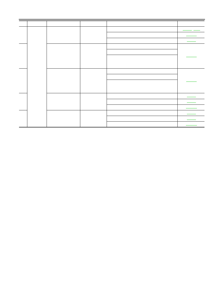
30
Others
Engine starts in posi-
tions other than “N” or
“P”.
ON vehicle
1. Ignition switch and starter
2. CVT position
3. Transmission range switch
31
When brake pedal is
depressed with igni-
tion switch ON, selec-
tor lever cannot be
shifted from “P” posi-
tion to other position.
ON vehicle
1. Stop lamp switch
2. Shift lock solenoid
3. CVT shift selector
32
When brake pedal is
not depressed with ig-
nition switch ON, se-
lector lever can be
shifted from “P” posi-
tion to other position.
ON vehicle
1. Stop lamp switch
2. Shift lock solenoid
3. CVT shift selector
33
Cannot be changed to
manual mode.
ON vehicle
1. Manual mode switch
2. CAN communication line
3. Combination meter
33
Cannot be changed to
“DS” mode.
ON vehicle
1. Manual mode switch
2. CAN communication line
3. Combination meter
No.
Item
Symptom
Condition
Diagnostic item
Reference