Content .. 1154 1155 1156 1157 ..
Nissan Maxima. Manual - part 1156
TM-88
< DTC/CIRCUIT DIAGNOSIS >
[CVT: RE0F09B]
P0841 TRANSMISSION FLUID PRESSURE SEN/SW A
P0841 TRANSMISSION FLUID PRESSURE SEN/SW A
Description
INFOID:0000000010113646
Using the engine load (throttle position), the primary pulley revolution speed, and the secondary pulley revolu-
tion speed as input signals, TCM changes the operating pressure of the primary pulley and the secondary pul-
ley and changes the groove width of the pulley to control the gear ratio.
DTC Logic
INFOID:0000000010113647
DTC DETECTION LOGIC
DTC CONFIRMATION PROCEDURE
CAUTION:
Always drive vehicle at a safe speed.
NOTE:
Immediately after performing any “DTC CONFIRMATION PROCEDURE”, always turn ignition switch OFF.
Then wait at least 10 seconds before performing the next test.
1.
CHECK DTC DETECTION
With CONSULT
1. Turn ignition switch ON.
2. Select “Data Monitor” in “TRANSMISSION”.
3. Start engine and maintain the following conditions for at least 12 consecutive seconds.
Is “P0841” detected?
YES
>> Go to
NO
>> Check intermittent incident. Refer to
GI-41, "Intermittent Incident"
.
Diagnosis Procedure
INFOID:0000000010113648
1.
CHECK LINE PRESSURE
Perform line pressure test. Refer to
TM-162, "Inspection and Judgment"
.
Is the inspection result normal?
YES
>> .GO TO 2.
NO
>> Repair or replace damaged parts. Refer to
TM-162, "Inspection and Judgment"
.
2.
CHECK SECONDARY PRESSURE SENSOR SYSTEM
Check secondary pressure sensor system. Refer to
.
Is the inspection result normal?
YES
>> GO TO 3.
NO
>> Repair or replace damaged parts.
3.
CHECK PRIMARY PRESSURE SENSOR SYSTEM
Check primary pressure sensor system. Refer to
.
Is the inspection result normal?
YES
>> GO TO 4.
NO
>> Repair or replace damaged parts.
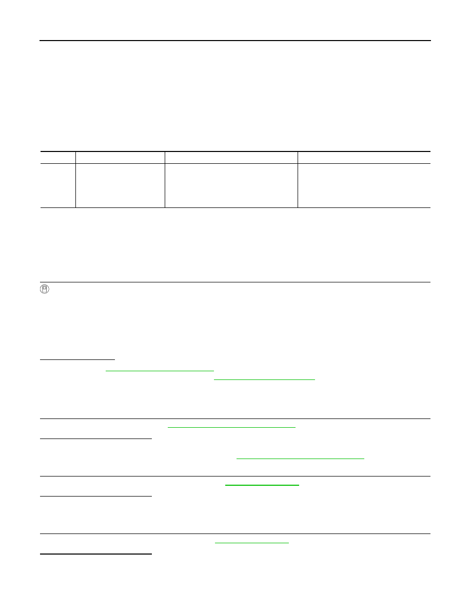
DTC
Trouble diagnosis name
DTC is detected if...
Possible cause
P0841
Transmission Fluid Pressure
Sensor/Switch A Circuit
Range/Performance
Correlation between the values of the trans-
mission fluid pressure sensor A (secondary
pressure sensor) and the transmission fluid
pressure sensor B (primary pressure sen-
sor) is out of specification.
• Harness or connectors
(Sensor circuit is open or shorted.)
• Secondary pressure sensor
• Primary pressure sensor
VEHICLE SPEED
: 40 km/h (25 MPH) or more
RANGE
: “D” position