Nissan Maxima. Manual - part 1155


  Index      Nissan     Nissan Maxima (2009-2014 year) - Service and Repair Manual


Search            


Content   ..  1153  1154  1155  1156   ..


Nissan Maxima. Manual - part 1155


TM-84

< DTC/CIRCUIT DIAGNOSIS >

[CVT: RE0F09B]

P0826 UP AND DOWN SHIFT SW

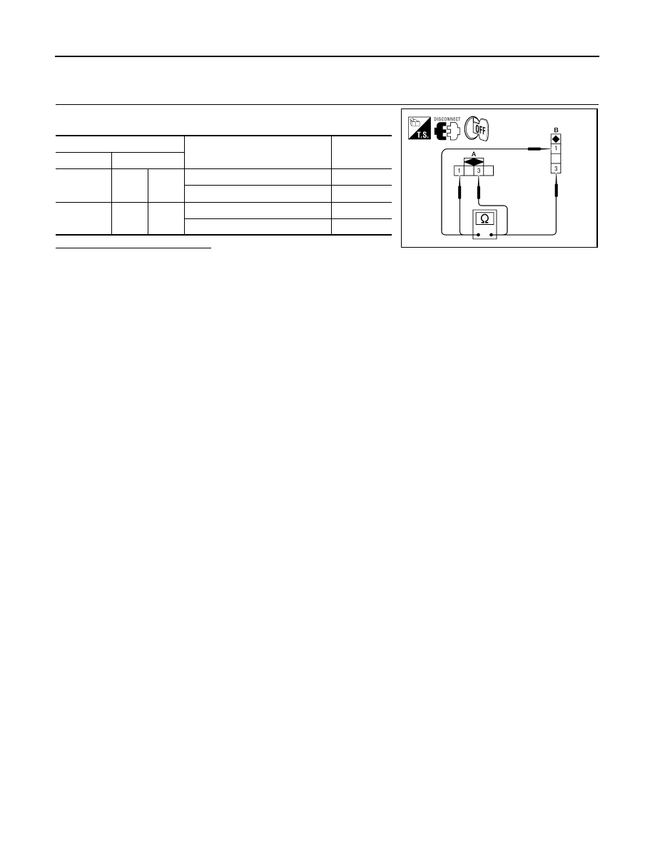
Component Inspection (Paddle Shifter)

INFOID:0000000010113642

1.

CHECK PADDLE SHIFTER

Check continuity between paddle shifter connector terminals.

Is the inspection result normal?

YES

>> INSPECTION END

NO

>> Repair or replace damaged parts.

Paddle shifter connector

Condition

Continuity

Connector

Terminal

M82 (A)

1

3

Pressed paddle shifter (shift-up)

Existed

Released paddle shifter

Not existed

M83 (B)

1

3

Pressed paddle shifter (shift-down)

Existed

Released paddle shifter

Not existed

AWDIA0609ZZ

P0840 TRANSMISSION FLUID PRESSURE SEN/SW A

TM-85

< DTC/CIRCUIT DIAGNOSIS >

[CVT: RE0F09B]

C

E

F

G

H

I

J

K

L

M

A

B

TM

N

O

P

P0840 TRANSMISSION FLUID PRESSURE SEN/SW A

Description

INFOID:0000000010113643

The secondary pressure sensor detects secondary pressure of CVT and sends a signal to the TCM.

DTC Logic

INFOID:0000000010113644

DTC DETECTION LOGIC

DTC CONFIRMATION PROCEDURE

NOTE:

Immediately after performing any “DTC CONFIRMATION PROCEDURE”, always turn ignition switch OFF.

Then wait at least 10 seconds before performing the next test.

1.

CHECK DTC DETECTION

With CONSULT

1. Turn ignition switch ON.

2. Select “Data Monitor” in “TRANSMISSION”.

3. Check that output voltage of CVT fluid temperature sensor is within the range below.

4. Start engine and wait for at least 5 consecutive seconds.

With GST

Follow the procedure “With CONSULT”.
Is “P0840” detected?

YES

>> Go to 

TM-85, "Diagnosis Procedure"

.

NO

>> Check intermittent incident. Refer to 

GI-41, "Intermittent Incident"

.

Diagnosis Procedure

INFOID:0000000010113645

Regarding Wiring Diagram information, refer to 

TM-126, "Wiring Diagram"

.

1.

CHECK INPUT SIGNAL

1. Start engine.

2. Check voltage between TCM connector terminal and ground.

Is the inspection result normal?

YES

>> GO TO 8.

NO

>> GO TO 2.

2.

CHECK POWER AND SENSOR GROUND

DTC

Trouble diagnosis name

DTC is detected if...

Possible cause

P0840

Transmission Fluid Pressure 
Sensor/Switch A Circuit

Signal voltage of the secondary pressure 
sensor is too high or too low while driving.

• Harness or connectors

(Sensor circuit is open or shorted.)

• Secondary pressure sensor

ATF TEMP SEN

: 1.0 – 2.0 V

If it is out of range, drive the vehicle to decrease the voltage (warm up the fluid) or stop engine to increase the voltage 
(cool down the fluid)

TCM connector

Ground

Condition

Voltage 

(Approx.)

Connector

Terminal

F15

15

“N” position idle

1.0 – 1.5 V

AWDIA0131ZZ

TM-86

< DTC/CIRCUIT DIAGNOSIS >

[CVT: RE0F09B]

P0840 TRANSMISSION FLUID PRESSURE SEN/SW A

Check voltage between TCM terminals.

Is the inspection result normal?

YES

>> GO TO 3.

NO

>> GO TO 5.

3.

CHECK HARNESS BETWEEN TCM AND CVT UNIT (SECONDARY PRESSURE SENSOR) (PART 1)

1. Turn ignition switch OFF.

2. Disconnect TCM connector and CVT unit connector.

3. Check continuity between TCM vehicle side harness connector

terminal and CVT unit vehicle side harness connector terminal.

Is the inspection result normal?

YES

>> GO TO 4.

NO

>> Repair or replace damaged parts.

4.

CHECK HARNESS BETWEEN TCM AND CVT UNIT (SECONDARY PRESSURE SENSOR) (PART 2)

Check continuity between TCM vehicle side harness connector ter-

minal and ground.

Is the inspection result normal?

YES

>> GO TO 7.

NO

>> Repair or replace damaged parts.

5.

CHECK HARNESS BETWEEN TCM AND CVT UNIT (SENSOR POWER AND SENSOR GROUND) (PART

1)
1. Turn ignition switch OFF.

2. Disconnect TCM connector and CVT unit connector.

3. Check continuity between TCM vehicle side harness connector

terminals and CVT unit vehicle side harness connector termi-

nals.

Is the inspection result normal?

YES

>> GO TO 6.

NO

>> Repair or replace damaged parts.

6.

CHECK HARNESS BETWEEN TCM AND CVT UNIT (SENSOR POWER AND SENSOR GROUND) (PART

TCM connector

Voltage (Approx.)

Connector

Terminal

F15

25

26

4.75 – 5.25 V

AWDIA0132ZZ

TCM vehicle side harness 

connector

CVT unit vehicle side harness 

connector

Continuity

Connector

Terminal

Connector

Terminal

F15 (A)

15

F46 (B)

23

Existed

AWDIA0133ZZ

TCM vehicle side harness connector

Ground

Continuity

Connector

Terminal

F15

15

Not existed

AWDIA0134ZZ

TCM vehicle side harness con-

nector

CVT unit vehicle side harness 

connector

Continuity

Connector

Terminal

Connector

Terminal

F15 (A)

25

F46 (B)

19

Existed

26

20

AWDIA0135ZZ

P0840 TRANSMISSION FLUID PRESSURE SEN/SW A

TM-87

< DTC/CIRCUIT DIAGNOSIS >

[CVT: RE0F09B]

C

E

F

G

H

I

J

K

L

M

A

B

TM

N

O

P

2)

Check continuity between TCM vehicle side harness connector ter-

minals and ground.

Is the inspection result normal?

YES

>> GO TO 7.

NO

>> Repair or replace damaged parts.

7.

CHECK TCM

1. Replace with the same type of TCM. Refer to 

TM-168, "Exploded View"

.

2. Connect each connector.

3. Perform “DTC CONFIRMATION PROCEDURE”. Refer to 

TM-85, "DTC Logic"

.

Is “P0840” detected?

YES

>> Replace transaxle assembly. Refer to 

TM-188, "Exploded View"

.

NO

>> Replace TCM. Refer to 

TM-168, "Exploded View"

.

8.

DETECT MALFUNCTIONING ITEMS

Check TCM connector pin terminals for damage or loose connection with harness connector.
Is the inspection result normal?

YES

>> Replace TCM. Refer to 

TM-168, "Exploded View"

.

NO

>> Repair or replace damaged parts.

TCM vehicle side harness connector

Ground

Continuity

Connector

Terminal

F15

25

Not existed

26

AWDIA0136ZZ


Content   ..  1153  1154  1155  1156   ..