Nissan Maxima. Manual - part 113


  Index      Nissan     Nissan Maxima (2009-2014 year) - Service and Repair Manual


Search            


Content   ..  111  112  113  114   ..


Nissan Maxima. Manual - part 113


AV-272

< ECU DIAGNOSIS INFORMATION >

[COLOR DISPLAY - W/O BOSE]

AV CONTROL UNIT

DTC Index

INFOID:0000000010064916

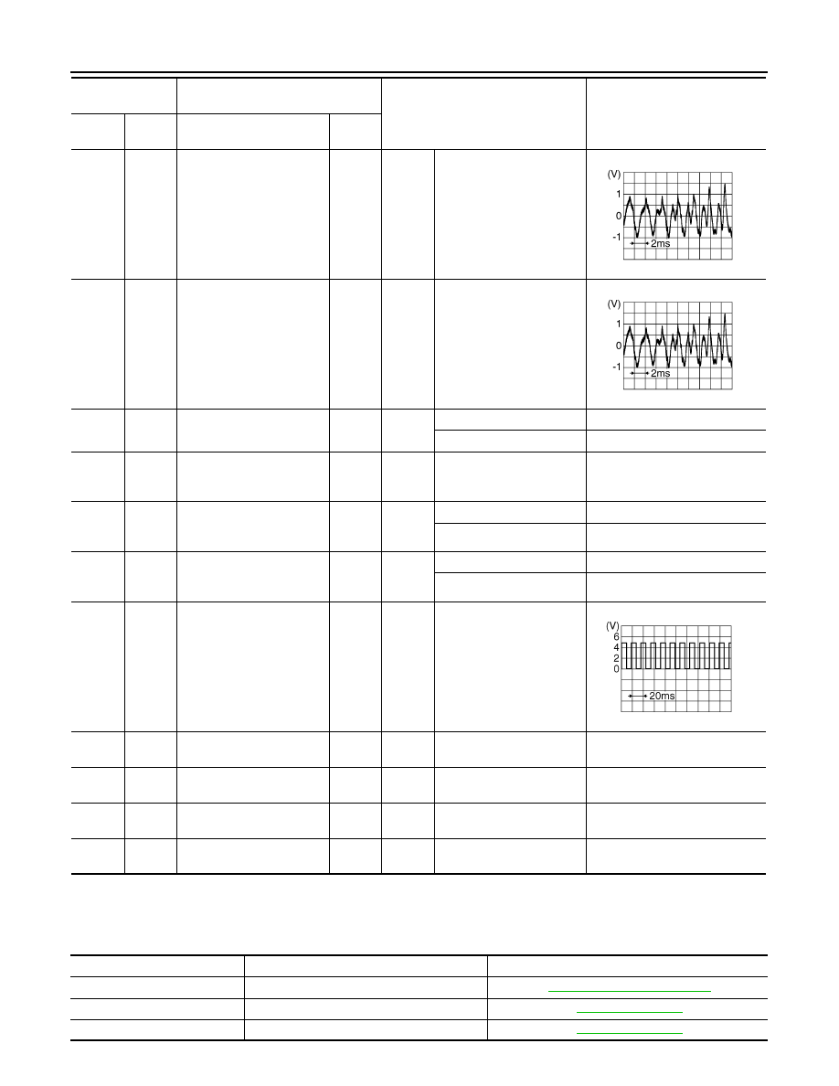
Self-diagnosis results display item

95

(B)

97

(R)

AUX audio signal RH

Input

Ignition 

switch 

ON

When AUX mode is select-
ed

96

(W)

97

(R)

AUX audio signal LH

Input

Ignition 

switch 

ON

When AUX mode is select-
ed

103

(SB)

Ground CD eject signal

Input

Pressing the eject switch

0V

Except for above

3.3V

104

(G)

Ground Ignition signal

Input

Ignition 

switch 

ON

Battery voltage

105

(P/B)

Ground Reverse signal

Input

Ignition 

switch 

ON

R position

Battery voltage

Other than R position

0V

106

(G/R)

Ground Parking brake signal

Input

Ignition 

switch 

ON

Parking brake ON

0V

Parking brake OFF

Battery voltage

107

(V/W)

Ground

Vehicle speed signal
 (8-pulse)

Input

Ignition 

switch 

ON

When vehicle speed is ap-
prox. 25 MPH (40 km/h)

120

(B)

USB ground

121
(W)

USB D-

122

(R)

V BUS signal

123

(G)

USB D+

Terminal

(Wire color)

Description

Condition

Reference value

(Approx.)

+

Signal name

Input/

Output

SKIB3609E

SKIB3609E

SKIA6649J

DTC

Display item

Refer to

U1000

CAN COMM CIRCUIT [U1000]

AV-206, "Diagnosis Procedure"

U1010

CONTROL UNIT (CAN) [1010]

AV-207, "DTC Logic"

U1200

Cont Unit [U1200]

AV-208, "DTC Logic"

AV

AV CONTROL UNIT

AV-273

< ECU DIAGNOSIS INFORMATION >

[COLOR DISPLAY - W/O BOSE]

C

D

E

F

G

H

I

J

K

L

M

B

A

O

P

U1216

CAN CONT [U1216]

AV-209, "DTC Logic"

U1218

HDD CONN [U1218]

AV-210, "DTC Logic"

U1219

HDD READ [U1219]

AV-211, "DTC Logic"

U121A

HDD WRITE [U121A]

AV-212, "DTC Logic"

U121B

HDD COMM [U121B]

AV-213, "DTC Logic"

U121C

HDD ACCESS [U121C]

AV-214, "DTC Logic"

U121D

DSP CONN [U121D]

AV-215, "Diagnosis Procedure"

U121E

DSP COMM [U121E]

AV-216, "Diagnosis Procedure"

U1225

USB CONTROLLER [U1225]

AV-217, "DTC Logic"

U1227

DVD COMM [U1227]

AV-218, "Diagnosis Procedure"

U1228

SUB CPU CONN [U1228]

AV-219, "DTC Logic"

U1229

iPod CERTIFICATION [U1229]

AV-220, "DTC Logic"

U122A

CONFIG UNFINISH [U122A]

AV-221, "Diagnosis Procedure"

U122E

Built-in AUDIO CONN [U122E]

AV-222, "DTC Logic"

U1232

ST ANGLE SEN CALIB [1232]

AV-223, "Diagnosis Procedure"

U1243

FRONT DISP CONN [U1243]

AV-224, "Diagnosis Procedure"

U1255

SATELLITE TUNER [U1255]

AV-227, "Description"

U1263

USB OVERCURRENT [U1263]

AV-226, "Diagnosis Procedure"

U1310

CONTROL UNIT (AV) [U1310]

AV-230, "DTC Logic"

U1300
U1240

• AV COMM CIRCUIT [U1300]
• SWITCH CONN [U1240]

AV-229, "Description"

DTC

Display item

Refer to

AV-274

< ECU DIAGNOSIS INFORMATION >

[COLOR DISPLAY - W/O BOSE]

DISPLAY UNIT

DISPLAY UNIT

Reference Value

INFOID:0000000010064917

TERMINAL LAYOUT

PHYSICAL VALUES

AWNIA1727ZZ

Terminal

(Wire color)

Description

Condition

Reference value

(Approx.)

+

Signal name

Input/

Output

1

(B)

Ground Ground

Ignition 

switch 

ON 

0V

2

(Y)

Ground Inverter VCC

Input

Ignition 

switch 

ACC

9V

3

(O)

Ground Signal VCC

Input

Ignition 

switch 

ACC

9V

4

(B)

Ground AUX image ground

Ignition 

switch 

ON

0V

5

Shield

6

(R)

Ground RGB signal (G: green)

Input

Ignition 

switch 

ON

Start confirmation/adjust-
ment mode, and then dis-
play color bar by selecting 
“Color Spectrum Bar” on 
DISPLAY DIAGNOSIS 
screen.

7

Shield

8

(R)

Ground

Horizontal synchronizing 
(HP) signal

Output

Ignition 

switch 

ON

SKIB2236J

SKIB3601E

AV

DISPLAY UNIT

AV-275

< ECU DIAGNOSIS INFORMATION >

[COLOR DISPLAY - W/O BOSE]

C

D

E

F

G

H

I

J

K

L

M

B

A

O

P

9

(B)

Ground RGB area (YS) signal

Input

Ignition 

switch 

ON

At RGB image displayed

5V

At rear view camera image 
displayed

11

(Y)

Ground

Communication signal
(CONT

→DISP)

Input

Ignition 

switch 

ON

When adjusting display 
brightness

13

(BR)

Ground Inverter ground

Ignition 

switch 

ON

0V

14

(LG)

Ground Signal ground

Ignition 

switch 

ON

0V

15

(W)

Ground AUX image signal

Input

Ignition 

switch 

ON

When AUX mode is select-
ed

17

(B)

Ground RGB signal (R: red)

Input

Ignition 

switch 

ON

Start confirmation/adjust-
ment mode, and then dis-
play color bar by selecting 
“Color Spectrum Bar” on 
DISPLAY DIAGNOSIS 
screen.

18

(W)

Ground RGB signal (B: blue)

Input

Ignition 

switch 

ON

Start confirmation/adjust-
ment mode, and then dis-
play color bar by selecting 
“Color Spectrum Bar” on 
DISPLAY DIAGNOSIS 
screen.

Terminal

(Wire color)

Description

Condition

Reference value

(Approx.)

+

Signal name

Input/

Output

PKIB4948J

PKIB5039J

SKIB2251J

SKIB2238J

SKIB2237J


Content   ..  111  112  113  114   ..