Nissan Maxima. Manual - part 1119


  Index      Nissan     Nissan Maxima (2009-2014 year) - Service and Repair Manual


Search            


Content   ..  1117  1118  1119  1120   ..


Nissan Maxima. Manual - part 1119


TELESCOPIC MOTOR

ST-21

< REMOVAL AND INSTALLATION >

C

D

E

F

H

I

J

K

L

M

A

B

ST

N

O

P

The tilt/telescope switch can remain attached to the side cover.

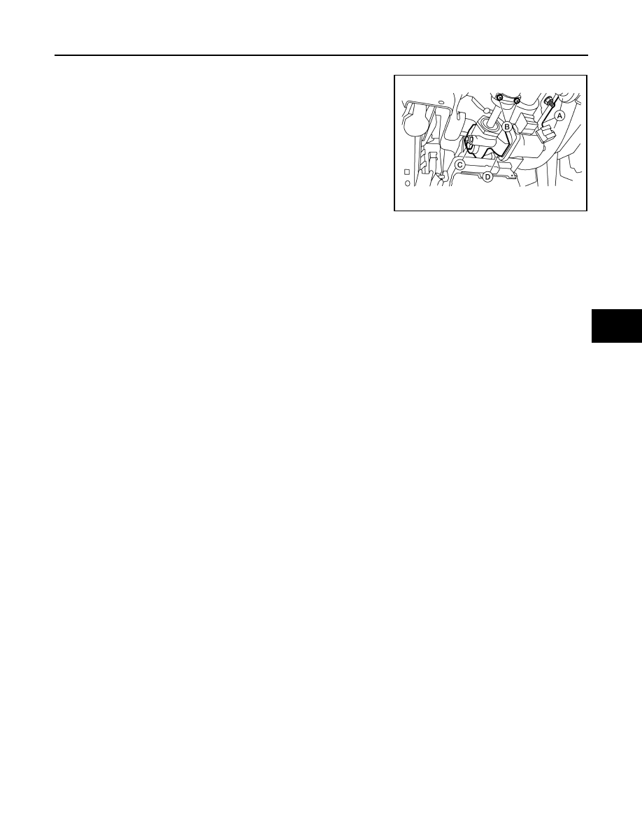
5. Remove telescope motor as follows.

1. Disconnect the harness connector (A) from the telescope

motor.

2. Remove the two telescope motor link screws (B) and tele-

scope motor link bracket.

3. Remove telescope motor bolt (C).

4. Remove the telescope motor (D).

NOTE:

If the steering wheel could not be telescoped to full out posi-

tion manually pull steering wheel to the full out position.

INSTALLATION

Installation is in the reverse order of removal.

NOTE:

• Adjust the telescope motor link to full out position and adjust as needed to fit into proper installed position.

• Inform customer that they will need to reset their Automatic Drive Positioner (ADP) settings.

ALGIA0053ZZ

ST-22

< REMOVAL AND INSTALLATION >

STEERING COLUMN

STEERING COLUMN

Exploded View

INFOID:0000000009465778

Without Electric Motor

AWGIA0105GB

1-4.

Steering column assembly nut tight-
ening order

5.

Steering wheel

6.

Combination switch and spiral cable

7.

Steering column assembly

8.

Hole cover seal

9.

Herbie clip

10.

Hole cover

11. Lower shaft assembly

STEERING COLUMN

ST-23

< REMOVAL AND INSTALLATION >

C

D

E

F

H

I

J

K

L

M

A

B

ST

N

O

P

With Electric Motor

Removal and Installation

INFOID:0000000009465779

REMOVAL

Hole Cover Seal, Hole Cover and Lower Shaft Assembly

1. Set wheels to the straight-ahead position.
2. Remove lower side bolt (A) of lower shaft assembly (1).

• Steering gear (2)

3. Remove the instrument lower panel LH. Refer to 

IP-19, "Removal and Installation"

.

AWGIA0098GB

1-4.

Steering column assembly nut tight-
ening order

5.

Steering wheel

6.

Combination switch and spiral cable

7.

Steering column assembly

8.

Hole cover seal

9.

Herbie clip

10.

Hole cover

11. Lower shaft assembly

ALGIA0041ZZ

ST-24

< REMOVAL AND INSTALLATION >

STEERING COLUMN

4. Remove bolt (A) and nut (B) of column upper joint (2), then

remove lower shaft assembly (1).

CAUTION:

Do not reuse column upper joint nut.

5. Loosen herbie clip, then remove hole cover seal from hole

cover.

6. Remove nuts of hole cover, and then remove clamp and hole

cover from dash panel.

Steering Column Assembly

1. Set wheels to the straight-ahead position.
2. Remove instrument side finisher (LH). Refer to 

IP-10, "Exploded View"

.

3. Remove instrument lower panel LH. Refer to 

IP-19, "Removal and Installation"

.

4. Remove lower knee protector (LH) bolts (

)(, then remove

lower knee protector (LH) (1). Refer to 

IP-10, "Exploded View"

.

5. Remove steering column upper and lower covers. Refer to 

IP-

10, "Exploded View"

.

6. Remove combination switch and spiral cable. Refer to 

SR-15,

"Removal and Installation"

.

7. Disconnect each switch harness connector installed to steering

column assembly, and then disconnect harness clips from steer-

ing column assembly.

8. Remove bolt (A) and nut (B) of column upper joint (2).

• Lower shaft assembly (1)

CAUTION:

Do not reuse column upper joint nut.

9. Remove steering column assembly nuts, then remove steering

column assembly.

INSPECTION AFTER REMOVAL

Hole Cover Seal, Hole Cover and Lower Shaft Assembly

Check each part of hole cover seal, hole cover and steering column and lower shaft assembly for damage or

other malfunctions. Replace if necessary.

Steering Column Assembly

• Check each part of steering column assembly for damage or other malfunctions. Replace entire steering col-

umn assembly if any parts are damaged.

• Measure the length (L) as shown if vehicle has been involved in a

minor collision. Replace steering column assembly if outside the

specifications.

ALGIA0042ZZ

ALGIA0043ZZ

ALGIA0042ZZ

Steering column length (L)

: Refer to 

ST-37, "Steering 

Column"

SGIA1177E


Content   ..  1117  1118  1119  1120   ..