Nissan Maxima. Manual - part 1118


  Index      Nissan     Nissan Maxima (2009-2014 year) - Service and Repair Manual


Search            


Content   ..  1116  1117  1118  1119   ..


Nissan Maxima. Manual - part 1118


STEERING WHEEL

ST-17

< REMOVAL AND INSTALLATION >

C

D

E

F

H

I

J

K

L

M

A

B

ST

N

O

P

REMOVAL AND INSTALLATION

STEERING WHEEL

Removal and Installation

INFOID:0000000009465773

REMOVAL

NOTE:

When removing spiral cable, use tape so that the case and rotating part keep aligned. This will prevent neutral

position alignment procedure during spiral cable installation.
1. Set steering wheel to the straight-ahead position.
2. Remove driver air bag module. Refer to 

SR-12, "Removal and Installation"

.

3. Remove steering wheel lock nut after steering is locked.
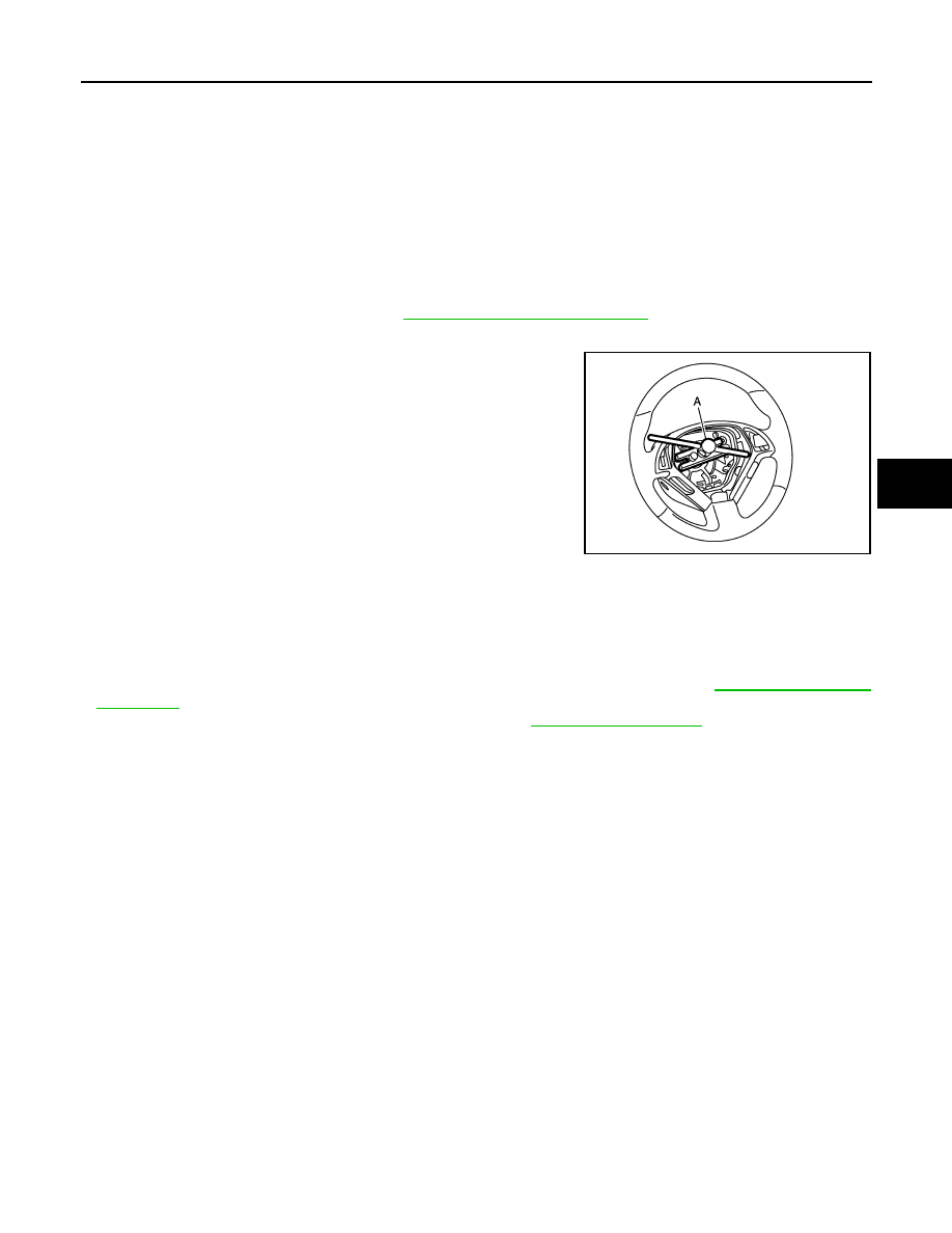
4. Remove steering wheel using Tool (A).

INSTALLATION

Installation is in the reverse order of removal.

CAUTION:

Do not rotate spiral cable freely or excessively when the steering wheel is removed. Doing so may

cause spiral cable damage.

NOTE:

• Check the spiral cable neutral position after replacing or rotating spiral cable. Refer to 

SR-15, "Removal and

Installation"

.

• Tighten the steering wheel lock nut to specification. Refer to 

ST-22, "Exploded View"

.

Tool number (A) : ST27180001 (J-25726-A)

JSGIA0341ZZ

ST-18

< REMOVAL AND INSTALLATION >

TILT MOTOR

TILT MOTOR

Exploded View

INFOID:0000000009465774

Removal and Installation

INFOID:0000000009465775

REMOVAL

1. Remove instrument lower panel LH. Refer to 

IP-19, "Removal and Installation"

.

2. Remove lower knee protector (LH) bolts (A) and the lower knee

protector (LH) (B).

3. Telescope the steering wheel to the full out position and tilt to highest position.

NOTE:

If either function is inoperative you can do this manually prior to installation.

4. Remove the steering column covers. Refer to 

IP-11, "Removal and Installation"

.

NOTE:

1.

Steering column assembly

2.

Telescope motor

3.

Telescope motor link bracket

4.

Tilt motor

5.

Tilt motor bolt cap

ALGIA0054GB

ALGIA0050ZZ

TILT MOTOR

ST-19

< REMOVAL AND INSTALLATION >

C

D

E

F

H

I

J

K

L

M

A

B

ST

N

O

P

The tilt/telescope switch can remain attached to the side cover.

5. Remove the tilt motor as follows.

1. Disconnect the harness connector (A) from the tilt motor. 

2. Remove the tilt motor link bolts (B).

3. Remove the tilt motor bolt (A) from the RH side of column.

4. Remove the tilt motor (B).

NOTE:

If the steering wheel could not be tilted to the highest position,

manually tilt steering wheel to the highest position.

INSTALLATION

Installation is in the reverse order of removal.

NOTE:

• When installing the tilt motor link bolts, manually move steering wheel up and down to align the bolt holes.

• Inform customer that they will need to reset their Automatic Drive Positioner (ADP) settings.

ALGIA0051ZZ

ALGIA0052ZZ

ST-20

< REMOVAL AND INSTALLATION >

TELESCOPIC MOTOR

TELESCOPIC MOTOR

Exploded View

INFOID:0000000009465776

Removal and Installation

INFOID:0000000009465777

REMOVAL

1. Remove instrument lower panel LH. Refer to 

IP-19, "Removal and Installation"

.

2. Remove lower knee protector (LH) bolts (A) and the lower knee

protector (LH) (B).

3. Telescope the steering wheel to the full out position and tilt to highest position.

NOTE:

If either function is inoperative you can do this manually prior to installation.

4. Remove the steering column covers. Refer to 

IP-11, "Removal and Installation"

.

NOTE:

1.

Steering column assembly

2.

Telescope motor

3.

Telescope motor link bracket

4.

Tilt motor

5.

Tilt motor bolt cap

ALGIA0054GB

ALGIA0050ZZ


Content   ..  1116  1117  1118  1119   ..