Nissan Maxima. Manual - part 1092


  Index      Nissan     Nissan Maxima (2009-2014 year) - Service and Repair Manual


Search            


Content   ..  1090  1091  1092  1093   ..


Nissan Maxima. Manual - part 1092


SIDE AIR BAG (SATELLITE) SENSOR

SR-29

< REMOVAL AND INSTALLATION >

C

D

E

F

G

I

J

K

L

M

A

B

SR

N

O

P

SIDE AIR BAG (SATELLITE) SENSOR

Removal and Installation

INFOID:0000000009471850

CAUTION:

• Before servicing, turn ignition switch OFF, disconnect both battery terminals and wait at least 3 min-

utes.

• Do not use air tools or electric tools for servicing.

• Replace the satellite sensor of deployed SRS front side air bag and deployed SRS side curtain air

bag. 

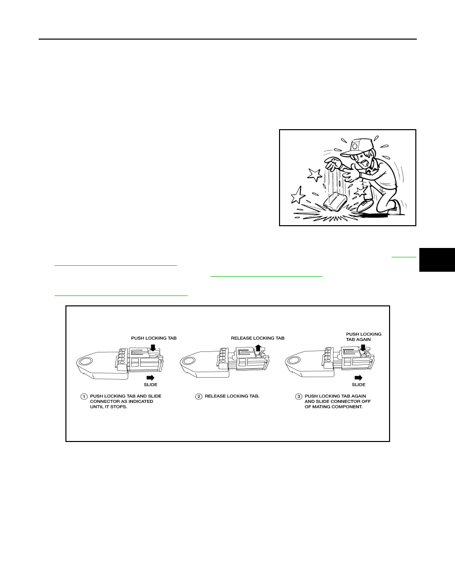
• Do not cause impact to the side air bag (satellite) sensor by

dropping etc. Replace the side air bag (satellite) sensor if it

has been dropped or sustained an impact.

REMOVAL

1. Disconnect the negative and positive battery terminals, then wait at least 3 minutes. Refer to 

PG-67,

"Removal and Installation (Battery)"

.

2. Remove the front seat belt retractor. Refer to 

SB-6, "Removal and Installation"

.

3. Disconnect the harness connector from the side air bag (satellite) sensor slide double locking. Refer to

SRC-9, "SRS Component Connectors"

.

JMHIA0009ZZ

AAMIA0498GB

SR-30

< REMOVAL AND INSTALLATION >

SIDE AIR BAG (SATELLITE) SENSOR

4. Remove the nuts (A), then remove side air bag (satellite) sensor

(2) from center pillar (1) studs.

: Front

(3): Side air bag (satellite) sensor slide double locking harness

connector.

INSTALLATION

Installation is in the reverse order of removal.

CAUTION:

• Do not use old nuts after removal; replace with new nuts.

• Be careful not to damage the satellite sensor harness.

• After the work is completed, make sure no system malfunction is detected by air bag warning lamp.

• In case a malfunction is detected by the air bag warning lamp, reset by the self-diagnosis function

and delete the memory by CONSULT. 

• If a malfunction is still detected after the above operation, perform self-diagnosis to repair malfunc-

tions. Refer to 

SRC-12, "SRS Operation Check"

.

ALHIA0132GB

DIAGNOSIS SENSOR UNIT

SR-31

< REMOVAL AND INSTALLATION >

C

D

E

F

G

I

J

K

L

M

A

B

SR

N

O

P

DIAGNOSIS SENSOR UNIT

Removal and Installation

INFOID:0000000009471851

WARNING:

• Before servicing, turn ignition switch OFF, disconnect both battery terminals and wait at least 3 min-

utes.

• Before disconnecting the air bag sensor unit harness connector, be sure to disconnect the harness

connector of each air bag module and pre-tensioner seat belt to prevent air bag deployment by static

electricity.

• Do not use air tools or electric tools for servicing.

• When replacing the air bag diagnosis sensor unit, always check with the parts department for the lat-

est parts information. Installing an incorrect air bag diagnosis sensor unit may or may not cause the

air bag warning lamp to illuminate and may cause incorrect deployment of the supplemental air bags

and seat belt pre-tensioner in a collision resulting in serious personal injury or death. 

REMOVAL

1. Always check the air bag diagnosis sensor unit ECU discriminated number (identification number) or part

number using CONSULT.

2. Disconnect the negative and positive battery terminals, then wait at least 3 minutes. Refer to 

PG-67,

"Removal and Installation (Battery)"

.

3. Disconnect the harness connectors for each of the following SRS components. Refer to 

SR-19, "Removal

and Installation"

 (Side curtain air bag module), 

SE-68, "Removal and Installation"

 (Side air bag module

with climate controlled seats) or 

SE-126, "Removal and Installation"

 (Side air bag module without climate

controlled seats), 

SB-6, "Removal and Installation"

 (Seat belt pre-tensioner).

4. Remove the center console. Refer to 

IP-21, "Disassembly and Assembly"

.

5. Disconnect the harness connectors from the diagnosis sensor unit.
6. Remove the bolts, then remove the diagnosis sensor unit.

CAUTION:

• Do not impact the air bag diagnosis sensor unit.

1.

Diagnosis sensor unit harness connector

2.

Diagnosis sensor unit shield

3.

Diagnosis sensor unit

A.

Diagnosis sensor unit bolts

Front

AWHIA0014GB

SR-32

< REMOVAL AND INSTALLATION >

DIAGNOSIS SENSOR UNIT

• Do not cause an impact to the diagnosis sensor unit by drop-

ping etc. Replace the diagnosis sensor unit if it has been

dropped or sustained an impact.

INSTALLATION

Installation is in the reverse order of removal.

CAUTION:

• Do not use old bolts after removal; replace with new bolts.

• Be careful not to damage the diagnosis sensor unit harness.

• After the work is completed, make sure no system malfunction is detected by air bag warning lamp.

• In case a malfunction is detected by the air bag warning lamp, reset by the self-diagnosis function

and delete the memory by CONSULT. 

• If a malfunction is still detected after the above operation, perform self-diagnosis to repair malfunc-

tions. Refer to 

SRC-12, "SRS Operation Check"

.

• After replacing the air bag diagnosis sensor unit, confirm using CONSULT that the ECU discrimi-

nated number (identification number) or part number of the new replacement air bag diagnosis sen-

sor unit matches the ECU discriminated number (identification number) or part number of the

replaced (old) air bag diagnosis sensor unit.

NOTE:

If the ECU discriminated number or part number of the new replacement air bag diagnosis sensor unit differs

from the ECU discriminated number or part number of the replaced air bag diagnosis sensor unit, reconfirm

the parts information and verify that the correct air bag diagnosis sensor unit was installed.

JMHIA0009ZZ


Content   ..  1090  1091  1092  1093   ..