Nissan Maxima. Manual - part 1091


  Index      Nissan     Nissan Maxima (2009-2014 year) - Service and Repair Manual


Search            


Content   ..  1089  1090  1091  1092   ..


Nissan Maxima. Manual - part 1091


SIDE AIR BAG MODULE

SR-25

< REMOVAL AND INSTALLATION >

C

D

E

F

G

I

J

K

L

M

A

B

SR

N

O

P

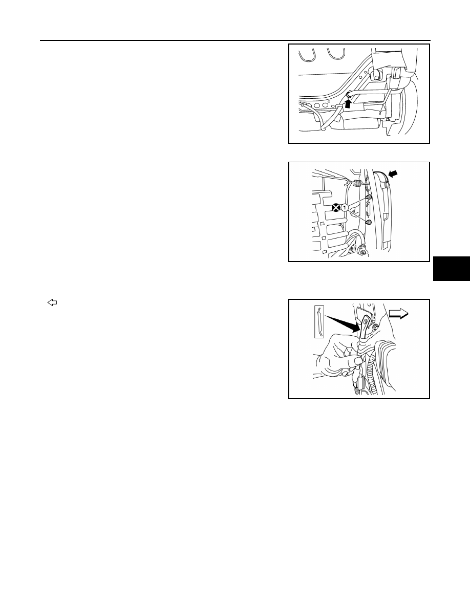
8. Disconnect the harness connector from the side air bag.
9. Remove and discard the two side air bag module nuts (1), then

remove the side air bag module. 

CAUTION:

Do not reuse the side air bag module nuts.

ASSEMBLY

Assembly is in the reverse order of disassembly. During assembly, note the following.

• Make sure the chute rod is properly positioned and installed as shown.

: Front

ALJIA0653ZZ

Air bag module nuts (1)

: 8.2 N·m (0.84 kg-m, 73 in-lb)

ALJIA0595ZZ

ALJIA0654ZZ

SR-26

< REMOVAL AND INSTALLATION >

SIDE AIR BAG MODULE

• Make sure the side air bag outer chute (7) is pulled over the side

air bag module (3) and the side air bag inner chute (4) is pulled

around the frame (2). Make sure there are no wrinkles and the

chutes are not folded, twisted or pinched.

(1) Seatback pad

(2) Frame

(3) Side air bag module

(4) Inner side air bag chute

(5) Chute rod

(6) Seatback board

(7) Outer chute

: Front

CAUTION:

• If a malfunction was detected by the air bag warning lamp, after repair or replacement of the mal-

function parts, reset the memory using self-diagnosis or CONSULT. 

• After work is completed, check that no system malfunction is detected by air bag warning lamp. 

• Make sure side air bag module shell is closed at all tabs and cushion of module is not exposed. Do

not reuse if the tab of shell is not secured.

• Always install new side air bag module attaching nuts and side air bag chute rod bolts. 

• Always route side air bag module harness in original location. Replace any deformed or damaged

clips with the same type and color. Always install clips in the original location on the harness. 

• Smooth out all wrinkles during assembly.

• Inspect seatback cushion, trim cover and trim cover chutes. Replace any damaged parts.

• Replace any deformed or damaged parts.

ALJIA0655ZZ

CRASH ZONE SENSOR

SR-27

< REMOVAL AND INSTALLATION >

C

D

E

F

G

I

J

K

L

M

A

B

SR

N

O

P

CRASH ZONE SENSOR

Component

INFOID:0000000009471848

Removal and Installation

INFOID:0000000009471849

CAUTION:

• Before servicing, turn ignition switch OFF, disconnect both battery terminals and wait at least 3 min-

utes.

• Do not use air tools or electric tools for servicing.

• Replace the crash zone sensor of deployed SRS driver air bag and deployed SRS front passenger air

bag. 

• Do not cause impact to the crash zone sensor by dropping

etc. Replace the crash zone sensor if it has been dropped or

sustained an impact.

REMOVAL

1. Disconnect the negative and positive battery terminals, then wait at least 3 minutes. Refer to 

PG-67,

"Removal and Installation (Battery)"

.

2. Remove the front air duct, then position upper radiator hose aside.

1.

Crash zone sensor harness connector

2.

Crash zone sensor

A.

Nut

Front

ALHIA0131GB

JMHIA0009ZZ

SR-28

< REMOVAL AND INSTALLATION >

CRASH ZONE SENSOR

3. Disconnect the harness connector the crash zone sensor.
4. Remove the nuts, then remove crash zone sensor.

INSTALLATION

Installation is in the reverse order of removal.

CAUTION:

• Do not use old crash zone sensor nuts after removal; replace with new nuts.

• Be careful not to damage the crash zone sensor harness.

• After the work is completed, make sure no system malfunction is detected by air bag warning lamp.

• In case a malfunction is detected by the air bag warning lamp, reset by the self-diagnosis function

and delete the memory by CONSULT. 

• If a malfunction is still detected after the above operation, perform self-diagnosis to repair malfunc-

tions. Refer to 

SRC-12, "SRS Operation Check"

.


Content   ..  1089  1090  1091  1092   ..