Nissan Maxima. Manual - part 1064


  Index      Nissan     Nissan Maxima (2009-2014 year) - Service and Repair Manual


Search            


Content   ..  1062  1063  1064  1065   ..


Nissan Maxima. Manual - part 1064


POWER SUPPLY AND GROUND CIRCUIT

SEC-81

< DTC/CIRCUIT DIAGNOSIS >

C

D

E

F

G

H

I

J

L

M

A

B

SEC

N

O

P

>> Work End.

IPDM E/R (INTELLIGENT POWER DISTRIBUTION MODULE ENGINE ROOM)
IPDM E/R (INTELLIGENT POWER DISTRIBUTION MODULE ENGINE ROOM) : Di-
agnosis Procedure

INFOID:0000000010068744

Regarding Wiring Diagram information, refer to 

PCS-28, "Wiring Diagram"

.

1.

 CHECK FUSES AND FUSIBLE LINK

Check that the following IPDM E/R fuses or fusible link are not blown.

Is the fuse blown?

YES

>> Replace the blown fuse or fusible link after repairing the affected circuit.

NO

>> GO TO 2

2.

 CHECK POWER SUPPLY CIRCUIT

1. Turn ignition switch OFF.

2. Disconnect IPDM E/R connectors.

3. Check voltage between IPDM E/R harness connector and ground.

Is the measurement value normal?

YES

>> GO TO 3

NO

>> Repair harness or connector.

3.

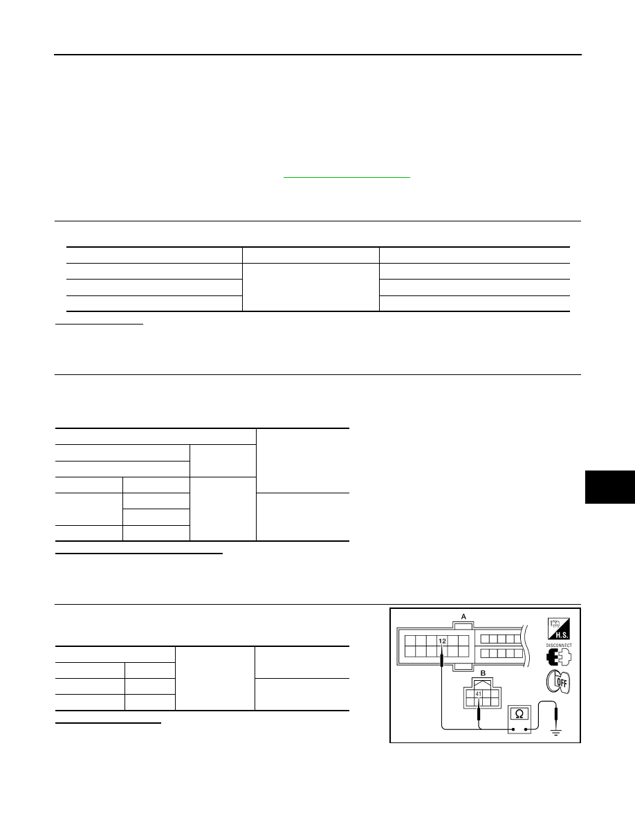
 CHECK GROUND CIRCUIT

Check continuity between IPDM E/R harness connectors and

ground.

Does continuity exist?

YES

>> Inspection End.

NO

>> Repair harness or connector.

Terminal No.

Signal name

Fuses and fusible link No.

1

Battery power supply

B

2

A, D

36

A, E, L

Terminals

Voltage (V)

(Approx.)

(+)

(

−)

IPDM E/R

Connector

Terminal

Ground

E16

1

Battery voltage

2

E18

36

IPDM E/R

Ground

Continuity

Connector

Terminal

A: E18

12

Yes

B: E17

41

ALCIA0034ZZ

SEC-82

< DTC/CIRCUIT DIAGNOSIS >

KEY SLOT

KEY SLOT

Diagnosis Procedure

INFOID:0000000010052008

Regarding Wiring Diagram information, refer to 

SEC-147, "Wiring Diagram"

 or 

SEC-128, "Wiring Diagram"

.

1.

CHECK KEY SLOT POWER SUPPLY CIRCUIT

1. Turn ignition switch OFF.

2. Disconnect key slot connector.

3. Check voltage between slot harness connector M40 terminal 1,

5 and ground.

Is the inspection result normal?

YES

>> GO TO 2

NO

>> Repair or replace key slot power supply circuit.

2.

CHECK KEY SLOT GROUND CIRCUIT

Check continuity between key slot harness connector M40 terminal

7 and ground.

Is the inspection result normal?

YES

>> GO TO 3

NO

>> Repair or replace key slot ground circuit.

3.

CHECK INTERMITTENT INCIDENT

Refer to 

GI-41, "Intermittent Incident"

.

>> Inspection End.

Key slot

Ground

Voltage (V)

(Approx.)

Connector

Terminal

M40

1

Ground

Battery voltage

5

ALKIA0419ZZ

Key slot

Ground

Continuity

Connector

Terminal

M40

7

Ground

Yes

ALKIA0420ZZ

KEY SLOT ILLUMINATION

SEC-83

< DTC/CIRCUIT DIAGNOSIS >

C

D

E

F

G

H

I

J

L

M

A

B

SEC

N

O

P

KEY SLOT ILLUMINATION

Description

INFOID:0000000010052009

Blinks when Intelligent Key insertion is required.

Component Function Check

INFOID:0000000010052010

1.

CHECK FUNCTION

 With CONSULT

Check key slot illumination (“KEY SLOT ILLUMI”) Active Test mode.

Is the inspection result normal?

YES

>> Key slot function is OK.

NO

>> Refer to 

SEC-83, "Diagnosis Procedure"

.

Diagnosis Procedure

INFOID:0000000010052011

Regarding Wiring Diagram information, refer to 

SEC-147, "Wiring Diagram"

 or 

SEC-128, "Wiring Diagram"

.

1.

CHECK KEY SLOT ILLUMINATION OUTPUT SIGNAL 

Check voltage between key slot harness connector M40 terminal 6

and ground.

Is the inspection result normal?

YES

>> GO TO 6

NO

>> GO TO 2

2.

CHECK KEY SLOT POWER SUPPLY CIRCUIT

1. Turn ignition switch OFF.

2. Disconnect key slot connector.

ALKIA0418ZZ

Terminals

Condition

Key slot

illumination

Voltage (V)         

 (Approx.)

(+)

(–)

Key slot 

connector

Terminal

M40

6

Ground

Intelligent Key inserted

OFF

Battery voltage

Intelligent Key removed

ON

0

SEC-84

< DTC/CIRCUIT DIAGNOSIS >

KEY SLOT ILLUMINATION

3. Check voltage between slot harness connector M40 terminal 1,

5 and ground.

Is the inspection result normal?

YES

>> GO TO 3

NO

>> Repair or replace key slot power supply circuit.

3.

CHECK KEY SLOT GROUND CIRCUIT

Check continuity between key slot harness connector M40 terminal

7 and ground.

Is the inspection result normal?

YES

>> GO TO 4

NO

>> Repair or replace key slot ground circuit.

4.

CHECK KEY SLOT CIRCUIT

1. Turn ignition switch OFF.

2. Disconnect BCM and key slot connector.

3. Check continuity between BCM harness connector M19 (A) ter-

minal 80 and key slot harness connector M40 (B) terminal 6.

4. Check continuity between BCM harness connector M19 (A) ter-

minal 80 and ground.

Is the inspection result normal?

YES

>> GO TO 5

NO

>> Repair or replace harness between BCM and key slot.

5.

CHECK KEY SLOT 

Refer to 

SEC-83, "Description"

.

Is the inspection result normal?

YES

>> GO TO 6

NO

>> Replace key slot. Refer to 

SEC-163, "Removal and Installation"

.

6.

CHECK INTERMITTENT INCIDENT 

Refer to 

GI-41, "Intermittent Incident"

.

>> Inspection End.

Terminals

Voltage (V)

(Approx.)

(+)

(–)

Key slot connector

Terminal

M40

1

Ground

Battery voltage

5

ALKIA0419ZZ

Key slot connec-

tor

Terminal

Ground

Continuity

M40

7

Yes

ALKIA0420ZZ

BCM connector

Terminal

Key slot 

connector

Terminal

Continuity

A: M19

80

B: M40

6

Yes

BCM connector

Terminal

Ground

Continuity 

A: M19

80

No

ALKIA0421ZZ


Content   ..  1062  1063  1064  1065   ..