Content .. 1056 1057 1058 1059 ..
Nissan Maxima. Manual - part 1058
B2603 SHIFT POSITION STATUS
SEC-57
< DTC/CIRCUIT DIAGNOSIS >
C
D
E
F
G
H
I
J
L
M
A
B
SEC
N
O
P
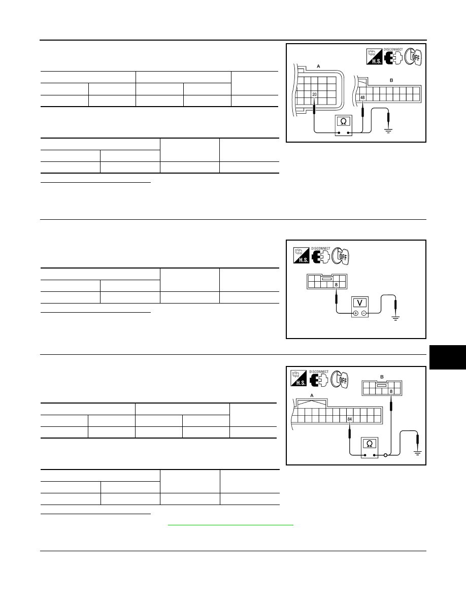
3. Check continuity between TCM harness connector F15 (A) ter-
minal 20 and BCM harness connector M18 (B) terminal 48.
4. Check continuity between TCM harness connector F15 (A) ter-
minal 20 and ground.
Is the inspection result normal?
YES
>> GO TO 3.
NO
>> Repair harness or connector.
3.
CHECK CVT SHIFT SELECT POWER SUPPLY
1. Turn ignition switch OFF.
2. Disconnect CVT shift selector harness connector.
3. Check voltage between CVT shift selector harness connector
M78 terminal 8 and ground.
Is the inspection result normal?
YES
>> GO TO 5.
NO
>> GO TO 4.
4.
CHECK CVT SHIFT SELECTOR POWER SUPPLY CIRCUIT
1. Disconnect BCM harness connector.
2. Check continuity between BCM harness connector M19 (A) ter-
minal 84 and CVT shift selector harness connector M78 (B) ter-
minal 8.
3. Check continuity between BCM harness connector M19 (A) ter-
minal 84 and ground.
Is the inspection result normal?
YES
>> Replace BCM. Refer to
BCS-79, "Removal and Installation"
NO
>> Repair harness or connector.
5.
CHECK CVT SHIFT SELECTOR CIRCUIT
1. Disconnect BCM harness connector.
TCM
BCM
Continuity
Connector
Terminal
Connector
Terminal
A: F15
20
B: M18
48
Yes
TCM
Ground
Continuity
Connector
Terminal
A: F15
20
Ground
No
ALKIA1317ZZ
CVT shift selector
Ground
Voltage [V]
Connector
Terminal
M78
8
Ground
Battery voltage
ALKIA0444ZZ
BCM
CVT shift selector
Continuity
Connector
Terminal
Connector
Terminal
A: M19
84
B: M78
8
Yes
BCM
Ground
Continuity
Connector
Terminal
A: M19
84
Ground
No
ALKIA0445ZZ