Nissan Maxima. Manual - part 1055


  Index      Nissan     Nissan Maxima (2009-2014 year) - Service and Repair Manual


Search            


Content   ..  1053  1054  1055  1056   ..


Nissan Maxima. Manual - part 1055


B2555 STOP LAMP

SEC-45

< DTC/CIRCUIT DIAGNOSIS >

C

D

E

F

G

H

I

J

L

M

A

B

SEC

N

O

P

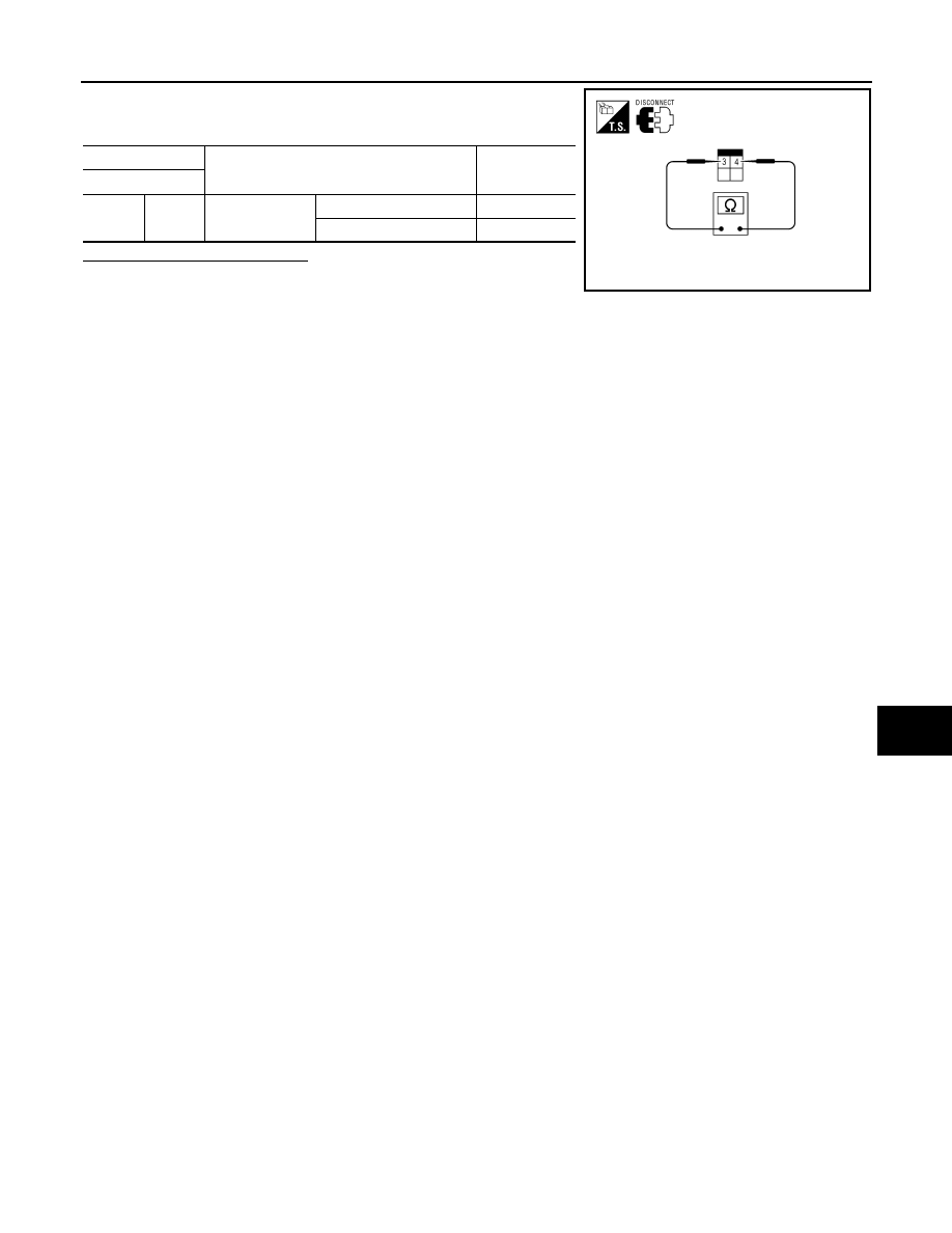
3. Check continuity between stop lamp switch terminals under the

following conditions.

Is the inspection result normal?

YES

>> Inspection End.

NO

>> Replace stop lamp switch.

Stop lamp switch

Condition

Continuity

Terminal

3

4

Brake pedal

Not depressed

No

Depressed

Yes

AWDIA0419ZZ

SEC-46

< DTC/CIRCUIT DIAGNOSIS >

B2556 PUSH-BUTTON IGNITION SWITCH

B2556 PUSH-BUTTON IGNITION SWITCH

Description

INFOID:0000000010051949

The switch that changes the power supply position. BCM maintains the power supply position status. BCM

changes the power supply position with the operation of the push-button ignition switch.

DTC Logic

INFOID:0000000010051950

DTC DETECTION LOGIC

DTC CONFIRMATION PROCEDURE

1.

PERFORM DTC CONFIRMATION PROCEDURE

1. Start the engine and wait for at least 100 seconds.

2. Check “Self Diagnostic Result” with CONSULT.
Is DTC detected?

YES

>> Refer to 

SEC-46, "Diagnosis Procedure"

.

NO

>> Inspection End.

Diagnosis Procedure

INFOID:0000000010051951

Regarding Wiring Diagram information, refer to 

SEC-147, "Wiring Diagram"

 or 

SEC-128, "Wiring Diagram"

.

1.

CHECK PUSH-BUTTON IGNITION SWITCH INPUT SIGNAL

1. Turn ignition switch OFF.

2. Disconnect push-button ignition switch harness connector.

3. Check voltage between push-button ignition switch harness con-

nector M38 terminal 4 and ground.

Is the inspection result normal?

YES

>> GO TO 2

NO

>> GO TO 4

2.

CHECK PUSH-BUTTON IGNITION SWITCH

Refer to 

SEC-47, "Component Inspection"

.

Is the inspection result normal?

YES

>> GO TO 3

NO

>> Replace push-button ignition switch. Refer to 

SEC-164, "Removal and Installation"

.

3.

CHECK INTERMITTENT INCIDENT

Refer to 

GI-41, "Intermittent Incident"

.

>> Inspection End.

DTC No.

Trouble diagnosis 

name

DTC detecting condition

Possible cause

B2556

PUSH-BUTTON IG-
NITION SWITCH

BCM detects the push-button ignition 
switch stuck to ON for 100 seconds or 
more.

• Harness or connectors

(Push-button ignition switch circuit is shorted.)

• Push-button ignition switch

Push-button ignition switch

Ground

Voltage [V]

Connector

Terminal

M38

4

Ground

Battery voltage

ALKIA1350ZZ

B2556 PUSH-BUTTON IGNITION SWITCH

SEC-47

< DTC/CIRCUIT DIAGNOSIS >

C

D

E

F

G

H

I

J

L

M

A

B

SEC

N

O

P

4.

CHECK PUSH-BUTTON IGNITION SWITCH CIRCUIT FOR SHORT

1. Disconnect BCM harness connector and IPDM E/R harness connector.

2. Check continuity between push-button ignition switch harness

connector M38 terminal 4 and ground.

Is the inspection result normal?

YES

>> Replace BCM. Refer to 

BCS-79, "Removal and Installa-

tion"

.

NO

>> Repair harness or connector.

Component Inspection

INFOID:0000000010051952

1.

CHECK PUSH-BUTTON IGNITION SWITCH

1. Turn ignition switch OFF.

2. Disconnect push-button ignition switch harness connector.

3. Check continuity between push-button ignition switch terminals

under the following conditions.

Is the inspection result normal?

YES

>> Inspection End.

NO

>> Replace push-button ignition switch. Refer to 

SEC-164,

"Removal and Installation"

.

Push-button ignition switch

Ground

Continuity

Connector

Terminal

M38

4

Ground

No

ALKIA0442ZZ

Push-button ignition switch

Condition

Continuity

Terminal

1

4

Pressed

Yes

Not pressed

No

ALKIA0443ZZ

SEC-48

< DTC/CIRCUIT DIAGNOSIS >

B2557 VEHICLE SPEED

B2557 VEHICLE SPEED

Description

INFOID:0000000010051953

BCM receives the 2 vehicle speed signals via CAN communication. One signal is transmitted by the “combina-

tion meter”. Another signal is transmitted by “ABS actuator and electric unit (control unit)”. BCM compares

both signals to detect the vehicle speed.

DTC Logic

INFOID:0000000010051954

DTC DETECTION LOGIC

NOTE:

• If DTC B2557 is displayed with DTC U1000, first perform the trouble diagnosis for DTC U1000. Refer to

SEC-29, "DTC Logic"

.

• If DTC B2557 is displayed with DTC U1010, first perform the trouble diagnosis for DTC U1010. Refer to

SEC-30, "DTC Logic"

.

DTC CONFIRMATION PROCEDURE

1.

PERFORM DTC CONFIRMATION PROCEDURE

1. Drive the vehicle at the vehicle speed of 10 km/h or more and wait for at least 10 seconds.

2. Check “Self Diagnostic Result” with CONSULT.
Is DTC detected?

YES

>> Refer to 

SEC-48, "Diagnosis Procedure"

.

NO

>> Inspection End.

Diagnosis Procedure

INFOID:0000000010051955

1.

CHECK DTC WITH “ABS ACTUATOR AND ELECTRIC UNIT (CONTROL UNIT)”

Check “Self Diagnostic Result” with CONSULT. Refer to 

BRC-82, "DTC No. Index"

.

Is the inspection result normal?

YES

>> GO TO 2

NO

>> Repair or replace malfunctioning parts.

2.

CHECK COMBINATION METER.

Check combination meter. Refer to 

MWI-4, "Work Flow"

.

>> Inspection End.

DTC

Self-diagnosis 

name

DTC detecting condition

Possible causes

B2557

VEHICLE 

SPEED

BCM detects the following difference between the vehicle 
speed from “combination meter” and the one from “ABS ac-
tuator and electric unit” for 10 seconds continuously
• One is 10 km/h or more and the other is 4 km/h or less.

• Wheel sensor
• Combination meter
• ABS actuator and electric 

unit (control unit)


Content   ..  1053  1054  1055  1056   ..