Content .. 1021 1022 1023 1024 ..
Nissan Maxima. Manual - part 1023
FRONT SEAT
SE-65
< REMOVAL AND INSTALLATION >
[WITH CLIMATE CONTROLLED SEATS]
C
D
E
F
G
H
I
K
L
M
A
B
SE
N
O
P
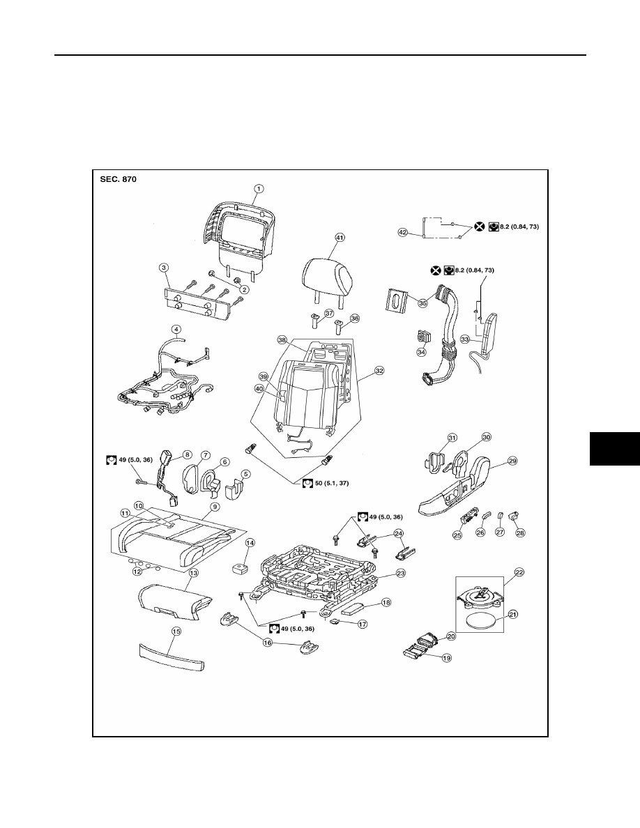
REMOVAL AND INSTALLATION
FRONT SEAT
Exploded View
INFOID:0000000009468144
DRIVER
Driver Seat - With Climate Controlled Seats
AWJIA0925ZZ
1.
Seatback board
2.
Seatback board clip
3.
Seat cushion lower rear finisher
4.
Seat harness
5.
Seat cushion inner finisher inside (RH) 6.
Recline mechanism inner cover
7.
Seat cushion outer finisher (RH)
8.
Seat belt buckle
9.
Seat cushion assembly