Nissan Maxima. Manual - part 102


  Index      Nissan     Nissan Maxima (2009-2014 year) - Service and Repair Manual


Search            


Content   ..  100  101  102  103   ..


Nissan Maxima. Manual - part 102


AV-228

< DTC/CIRCUIT DIAGNOSIS >

[COLOR DISPLAY - W/O BOSE]

U1255 SATELLITE RADIO TUNER

Is the inspection result normal?

YES

>> GO TO 3.

NO

>> Repair harness or connector.

3.

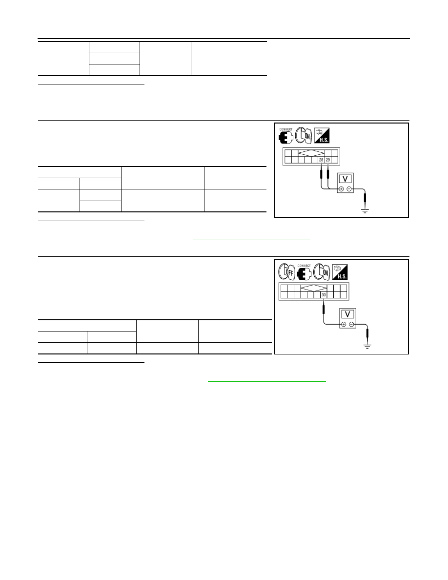
CHECK AV CONTROL UNIT VOLTAGE

1. Connect AV control unit connector.

2. Turn ignition switch ON.

3. Check voltage between AV control unit harness connector M116

and ground.

Is the inspection result normal?

YES

>> GO TO 4.

NO

>> Replace AV control unit. Refer to 

AV-311, "Removal and Installation"

.

4.

CHECK SATELLITE RADIO TUNER

1. Turn ignition switch OFF.

2. Disconnect AV control unit connector.

3. Connect satellite radio tuner.

4. Turn ignition switch ON.

5. Check voltage between satellite radio tuner harness connector

terminal ground.

Is the inspection result normal?

YES

>> Inspection End.

NO

>> Replace satellite radio tuner. Refer to 

AV-324, "Removal and Installation"

.

M116

28

Ground

No

29

30

(+)

(

−)

Voltage

(Approx.)

Connector

Terminals

M116

28

Ground

7.0V

29

ALNIA1179ZZ

(+)

(

−)

Voltage

(Approx.)

Connector

Terminal

B111

30

Ground

7.0V

ALNIA1180ZZ

AV

U1300 AV COMM CIRCUIT

AV-229

< DTC/CIRCUIT DIAGNOSIS >

[COLOR DISPLAY - W/O BOSE]

C

D

E

F

G

H

I

J

K

L

M

B

A

O

P

U1300 AV COMM CIRCUIT

Description

INFOID:0000000010064870

U1300 is indicated when a communication signal malfunction occurs. U1300 is indicated along with DTCs that

identify components connected to the AV control unit through communication lines. Determine the possible

malfunction cause from the table below.

SELF-DIAGNOSIS RESULTS DISPLAY ITEM

DTC

Display contents of 

CONSULT

DTC Detection Condition

Possible causes

U1300
U1240

• AV COMM CIRCUIT 

[U1300]

• SWITCH CONN 

[U1240]

When either one of the following items are detected:
• A/C and AV switch assembly power supply and ground 

circuits are malfunctioning.

• AV communication circuits between AV control unit and 

A/C and AV switch assembly are malfunctioning.

• AV communication signal between AV control unit and 

A/C and AV switch assembly is malfunctioning.

• A/C and AV switch assembly power 

supply and ground circuits.

• AV communication circuits be-

tween AV control unit and A/C and 
AV switch assembly.

AV-230

< DTC/CIRCUIT DIAGNOSIS >

[COLOR DISPLAY - W/O BOSE]

U1310 AV CONTROL UNIT

U1310 AV CONTROL UNIT

Description

INFOID:0000000010064871

Replace the AV control unit if this DTC is displayed. Refer to 

AV-311, "Removal and Installation"

.

DTC Logic

INFOID:0000000010064872

Part name

Description

AV CONTROL UNIT

• It is the master unit of the MULTI AV system  and it is connected to each control 

unit by means of communication. It operates each system according to com-
munication signals from the AV control unit.

• AV control unit includes audio function and vehicle information function.
• It is connected to ECM and combination meter via CAN communication to ob-

tain necessary information for the vehicle information function.

• It inputs the automatic brightness ON/OFF signals that are required for the dis-

play dimming control.

• It inputs the signals for driving status recognition (vehicle speed, reverse and 

parking brake). 

DTC

Display contents of 

CONSULT

DTC Detection Condition

Action to take

U1310

CONTROL UNIT (AV)
[U1310]

An initial diagnosis error is detected in AV communication 
circuit.

Replace AV control unit. Refer to 

AV-

311, "Removal and Installation"

.

AV

POWER SUPPLY AND GROUND CIRCUIT

AV-231

< DTC/CIRCUIT DIAGNOSIS >

[COLOR DISPLAY - W/O BOSE]

C

D

E

F

G

H

I

J

K

L

M

B

A

O

P

POWER SUPPLY AND GROUND CIRCUIT

AV CONTROL UNIT
AV CONTROL UNIT : Diagnosis Procedure

INFOID:0000000010064873

Regarding Wiring Diagram information, refer to 

AV-282, "Wiring Diagram - Without BOSE Audio System With-

out Navigation System"

.

1.

CHECK FUSES

Check that the following fuses of the AV control unit are not blown.

Are the fuses OK?

YES

>> GO TO 2.

NO

>> If fuse is blown, be sure to eliminate cause of malfunction before installing new fuse.

2.

POWER SUPPLY CIRCUIT CHECK

1. Disconnect AV control unit connectors M115 and M119. 

2. Check voltage between the AV control unit connectors M115

and M119 and ground.

Are the voltage results as specified?

YES

>> GO TO 3.

NO

>> • Check connector housings for disconnected or loose

terminals.

• Repair harness or connector.

3.

GROUND CIRCUIT CHECK

Unit

Terminals

Signal name

Fuse No.

AV control unit

19

Battery power

24

7

Ignition switch ACC or ON

17

104

Ignition switch ON or START

3

(+)

(-)

OFF

ACC

ON

Connector

Terminal

M115

7

Ground

0V

Battery 
voltage

Battery 
voltage

19

Ground

Battery 
voltage

Battery 
voltage

Battery 
voltage

M119

104

Ground

0V

0V

Battery 
voltage

AWNIA1581ZZ


Content   ..  100  101  102  103   ..