Nissan Maxima. Manual - part 1002


  Index      Nissan     Nissan Maxima (2009-2014 year) - Service and Repair Manual


Search            


Content   ..  1000  1001  1002  1003   ..


Nissan Maxima. Manual - part 1002


RSU-10

< REMOVAL AND INSTALLATION >

SHOCK ABSORBER

Rear Suspension Bound Bumper and Shock Absorber Mount Seal

Check the rear suspension bound bumper and the shock absorber mount seal for cracks and damage.

Replace if necessary.

Rear Shock Absorber

• Check for uneven operation through a full stroke for both compression and extension.

• Check the rear shock absorber for deformation, cracks, or other damage. Replace if necessary.

• Check the piston rod for damage, uneven wear, and distortion. Replace if necessary.

• Check for oil leakage on the welded or gland packing portions.

ASSEMBLY

Installation is the reverse order of removal. For tightening torque, refer to 

RSU-15, "Exploded View"

.

CAUTION:

Do not reuse the piston rod lock nut.

Make sure the piston rod is not damaged when attaching components to the rear shock absorber.

Disposal

INFOID:0000000009471820

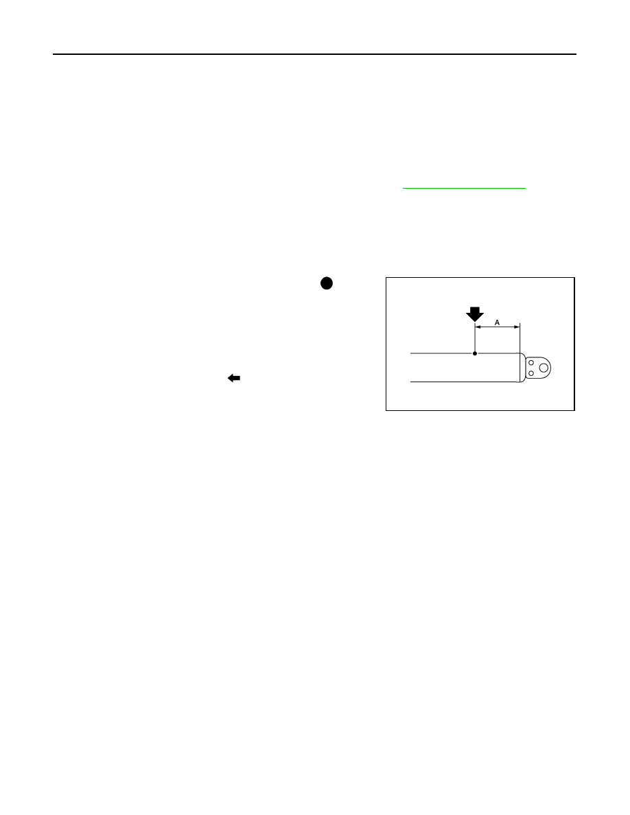
1. Set the rear shock absorber horizontally with the piston rod fully extended.
2. Drill 2 – 3 mm (0.08 – 0.12 in) hole at the position ( ) from top

as shown to release gas gradually.

CAUTION:

• Wear eye protection (safety glasses).

• Wear gloves.

• Be careful with metal chips or oil blown out by the com-

pressed gas.

NOTE:
• Drill vertically in this direction (

).

• Directly to the outer tube avoiding brackets.

• The gas is clear, colorless, odorless, and harmless.

3. Position the drilled hole downward and drain oil by moving the piston rod several times.

CAUTION:

Dispose of drained oil according to the law and local regulations.

(A)

: 20 – 30 mm (0.79 – 1.18 in)

NNEIB0021ZZ

FRONT LOWER LINK

RSU-11

< REMOVAL AND INSTALLATION >

C

D

F

G

H

I

J

K

L

M

A

B

RSU

N

O

P

FRONT LOWER LINK

Removal and Installation

INFOID:0000000009471821

Removal

1. Remove the front lower link nut and bolt from the rear axle hous-

ing using power tools.

2. Remove the adjusting bolt and nut from the rear suspension

member using power tools.

3. Remove the front lower link.

Installation

Installation is in the reverse order of removal.

CAUTION:

Do not reuse the adjusting nut.

Check the wheel alignment. Adjust as necessary. Refer to 

RSU-6, "Inspection and Adjustment"

.

LEIA0008E

RSU-12

< REMOVAL AND INSTALLATION >

RADIUS ROD

RADIUS ROD

Removal and Installation

INFOID:0000000009471822

Removal

1. Remove the rear wheel and tire using power tool. Refer to 

WT-60, "Adjustment"

.

2. Remove the radius rod nut and bolt from the rear axle housing using power tools.
3. Remove the radius rod bolt from the rear suspension member using power tools.
4. Remove the radius rod.

Installation

Installation is in the reverse order of removal.

CAUTION:

Do not reuse the radius rod nut at the rear axle housing.

Check the wheel alignment. Adjust as necessary. Refer to 

RSU-6, "Inspection and Adjustment"

.

REAR STABILIZER

RSU-13

< REMOVAL AND INSTALLATION >

C

D

F

G

H

I

J

K

L

M

A

B

RSU

N

O

P

REAR STABILIZER

Removal and Installation

INFOID:0000000009471823

Removal

1. Remove each rear stabilizer connecting rod nut using power tools.
2. Disconnect the rear stabilizer from each rear stabilizer connecting rod.
3. Remove each rear stabilizer clamp bolt using power tools.
4. Remove the rear stabilizer.
5. If necessary, remove each rear stabilizer clamp.
6. If necessary, remove each rear stabilizer bushing.

Installation

Installation is in the reverse order of removal.

• Make sure each slit in the surface of each rear stabilizer bushing faces the rear of the vehicle.

• Use a wrench to hold each rear stabilizer connecting rod ball stud while tightening each rear stabilizer con-

necting rod nut.

LEIA0050E


Content   ..  1000  1001  1002  1003   ..