Nissan Maxima. Manual - part 95


  Index      Nissan     Nissan Maxima (2009-2014 year) - Service and Repair Manual


Search            


Content   ..  93  94  95  96   ..


Nissan Maxima. Manual - part 95


AV-200

< SYSTEM DESCRIPTION >

[COLOR DISPLAY - W/O BOSE]

DIAGNOSIS SYSTEM (AV CONTROL UNIT)

Camera Cont.

The two functions of “Connection Confirmation” and “Adjust Offset of Rear View Camera” are available.

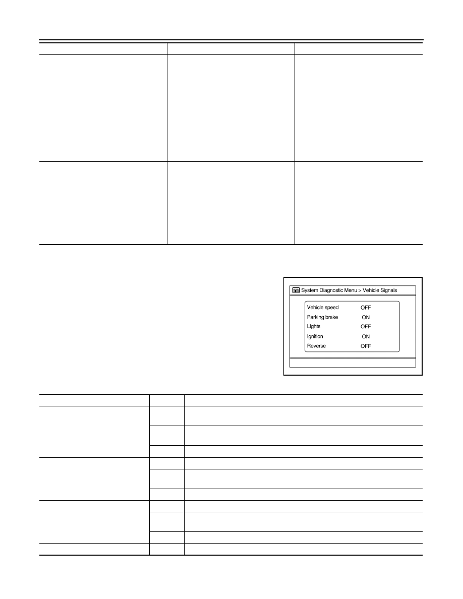
CONNECTION CONFIRMATION

The vehicle speed sensor, parking brake, park lights, ignition switch

and reverse sensor can be inspected.

ADJUST OFFSET OF REAR VIEW CAMERA

SAT Connection Error

When any one of the following items is de-
tected:
• satellite radio tuner power supply and 

ground circuits are malfunctioning.

• serial communication circuits between 

AV control unit and satellite radio tuner 
are malfunctioning.

• serial communication or request signal 

between AV control unit and satellite ra-
dio tuner is malfunctioning.

• request signal circuit between AV control 

unit and satellite radio tuner is malfunc-
tioning.

• Satellite radio tuner power supply and 

ground circuits.

• Serial communication circuits between 

AV control unit and satellite radio tuner.

• Request signal circuit between AV con-

trol unit and satellite radio tuner.

• AV COMM CIRCUIT
• Switches Connection Error

When any one of the following items is de-
tected:
• multifunction switch power supply and 

ground circuits are malfunctioning.

• AV communication circuits between AV 

control unit and multifunction switch are 
malfunctioning.

• AV communication signal between AV 

control unit and multifunction switch is 
malfunctioning.

• Multifunction switch power supply and 

ground circuits.

• AV communication circuits between AV 

control unit and multifunction switch.

Error item

Description

Possible malfunction factor/Action to take

AWNIA1744GB

Diagnosis item

Display

Vehicle status

Steer. Angle Sensor

ON

When steering the vehicle with ignition switch ON (remains ON until connection 
mode is stopped when it is turned ON).

OFF

• Ignition switch at ACC.
• No steering with ignition switch ON.

Malfunction detected in camera connection recognition signal.

Reverse Sensor

ON

Selector lever is in “R” with ignition switch ON.

OFF

• Ignition switch at ACC.
• Selector lever is in position other than “R” with ignition switch ON.

Malfunction detected in camera-connection recognition signal.

Vehicle Speed Sensor

ON

Vehicle speed is more than 0 km/h (0 MPH) with ignition switch ON.

OFF

• Ignition switch at ACC.
• Vehicle speed is 0 km/h (0 MPH) with ignition switch ON.

Malfunction detected in camera connection recognition signal.

Side view Switch

Not used.

AV

DIAGNOSIS SYSTEM (AV CONTROL UNIT)

AV-201

< SYSTEM DESCRIPTION >

[COLOR DISPLAY - W/O BOSE]

C

D

E

F

G

H

I

J

K

L

M

B

A

O

P

Use this mode to adjust the guide line display position of the rear-

view monitor if necessary after removing the rear view monitor cam-

era.

Vehicle CAN Diagnosis

• CAN communication status and error counter is displayed.

• The error counter displays “OK” if any malfunction was not

detected in the past and displays “0” if a malfunction is detected. It

increases by 1 if the status is normal at the next ignition switch ON

cycle. The upper limit of the counter is 39.

• The error counter is erased if reset.

AV COMM Diagnosis

• Displays the communication status between AV control unit (mas-

ter unit) and each unit.

• The error counter displays “OK” if any malfunction was not

detected in the past and displays “0” if a malfunction is detected. It

increases by 1 if the condition is normal at the next ignition switch

ON cycle. The upper limit of the counter is 39.

• If it resets, the error counter is erased.

Delete Unit Connection Log

Deletes any unit connection records and error records from the AV

control unit memory. (Clear the records of the unit that has been

removed.)

Initialize Settings

JSNIA0085GB

Items

Display (Current)

Malfunction counter

(Past)

Tx (HVAC)

OK / UNKWN

OK / 0 - 39

Rx (ECM)

OK / UNKWN

OK / 0 - 39

Rx (Cluster)

OK / UNKWN

OK / 0 - 39

Rx (HVAC)

OK / UNKWN

OK / 0 - 39

Rx (USM)

OK / UNKWN

OK / 0 - 39

Rx (STRG)

OK / UNKWN

OK / 0 - 39

AWNIA1967GB

Items

Status

(Current)

Counter

(Past)

C Tx(ITM-SW)

OK / UNKWN

OK / 0 - 39

C Rx(PrimarySW-ITM)

OK / UNKWN

OK / 0 - 39

C Rx(BTHF-ITM)

OK / UNKWN

OK / 0 - 39

AWNIA1978GB

JSNIA0154GB

A

V

- 2

0

2

< SYSTEM DESCRIPTION >

[COLOR DISPLAY - W/O BOSE]

DIAGNOSIS SYSTEM (AV CONTROL UNIT)

“Erase All Customer Data” and “Reset Factory Configuration” are

possible.

CAUTION:

• Never perform Reset Factory Configuration except when con-

figuration is unsuccessful. 

• Factory Configuration Initialize requires configuration. For

details, refer to 

AV-193, "Diagnosis Description"

.

CONSULT Function (MULTI AV)

INFOID:0000000010064830

APPLICATION ITEMS

CONSULT performs the following functions via the communication with the AV control unit.

AV Communication

When “AV communication” of “CAN Diag Support Monitor” is selected, the following function will be performed.

ECU IDENTIFICATION

The part number of AV control unit is displayed.

SELF DIAGNOSIS RESULT

• In CONSULT self-diagnosis, self-diagnosis results and error history are displayed collectively.

• The current malfunction indicates “CRNT”. The past malfunction indicates “PAST”.

• The timing is displayed as “0” if any of the error codes [U1000], [U1010], [U1300] and [U1310] is detected.

The counter increases by 1 if the condition is normal at the next ignition switch ON cycle.

Self-diagnosis Results Display Item

AWNIA2038GB

Diagnosis mode

Description

Ecu Identification

The part number of AV control unit can be checked.

Self Diagnostic Result

Performs a diagnosis on the AV control unit and a connection diagnosis for the communication 
circuit of the Multi AV system, and displays the current and past malfunctions collectively.

Data Monitor

The diagnosis of vehicle signal that is input to the AV control unit can be performed.

Configuration

• Read and save the vehicle specification.
• Write the vehicle specification when replacing AV control unit.

AV communication

AV&NAVI C/U

Displays the communication status from AV control unit to each unit as well as the error 
counter.

AUDIO

Displays the AV control unit communication status and the error counter.

Error item

Description

Possible malfunction factor/Action to take

CAN COMM CIRCUIT [U1000]

CAN communication malfunction is detect-
ed.

Perform diagnosis with CONSULT, and 
then repair the malfunctioning parts ac-
cording to the diagnosis results.
Refer to 

AV-206, "Diagnosis Procedure"

.

CONTROL UNIT (CAN) [U1010]

CAN initial diagnosis malfunction is detect-
ed.

Replace the AV control unit if the malfunc-
tion occurs constantly.

CONTROL UNIT (AV) [U1310]

AV communication circuit initial diagnosis 
malfunction is detected.

Cont Unit [U1200]

AV control unit malfunction is detected.

CAN CONT [U1216]

SUB CPU CONN [U1228]

iPod CERTIFICATION [U1229]

Built-in AUDIO CONN [U122E]

AV

DIAGNOSIS SYSTEM (AV CONTROL UNIT)

AV-203

< SYSTEM DESCRIPTION >

[COLOR DISPLAY - W/O BOSE]

C

D

E

F

G

H

I

J

K

L

M

B

A

O

P

DATA MONITOR

ALL SIGNALS

• Displays the status of the following vehicle signals inputted into the AV control unit.

• For each signal, actual signal can be compared with the condition recognized on the system.

HDD CONN [U1218]

AV control unit malfunction is detected.

• If the hard disk drive (HDD) is function-

ing normally, there is a possibility of a 
temporary malfunction.

• Replace the AV control unit if the mal-

function occurs constantly.

HDD READ [U1219]

HDD WRITE [U121A]

HDD COMM [U121B]

HDD ACCESS [U121C]

USB CONTROLLER [U1225]

USB connection malfunction is detected.

Check that the connection to the USB con-
nector is normal.

DSP CONN [U121D]

AV control unit malfunction is detected.

• If a disc can be played, then there is a 

possibility of the detection of a tempo-
rary malfunction.

• Replace the AV control unit if the mal-

function occurs constantly.

DSP COMM [U121E]

DVD COMM [U1227]

AV control unit malfunction is detected.

• If DVD can be played, then there is a 

possibility of the detection of a tempo-
rary malfunction.

• Replace the AV control unit if the mal-

function occurs constantly.

CONFIG UNFINISH [U122A]

The writing of configuration data is incom-
plete.

Write configuration data with CONSULT.

ST ANGLE SEN CALIB [U1232]

Predictive course line center position ad-
justment of the steering angle sensor is in-
complete.

Adjust the predictive course line center po-
sition of the steering angle sensor.

FRONT DISP CONN [U1243]

When either one of the following items are 
detected:
• Display unit power supply and ground 

circuits malfunction is detected.

• Communication circuits between AV 

control unit and display unit.

• Display unit power supply and ground 

circuits.

• Communication circuits between AV 

control unit and AV display unit.

SAT CONN [U1255]

Satellite radio tuner malfunction is detect-
ed.

Replace the satellite radio tuner if the mal-
function occurs constantly.

USB OVERCURRENT [U1263]

Detection of over current in USB connect-
er.

Check USB harness between the AV con-
trol unit and USB connector.

• AV COMM CIRCUIT [U1300]
• SWITCH CONN [U1240]

When either one of the following items are 
detected:
• Multifunction switch power supply and 

ground circuits are malfunctioning.

• AV communication circuits between AV 

control unit and multifunction switch are 
malfunctioning.

• Multifunction switch power supply and 

ground circuits.

• AV communication circuits between AV 

control unit and multifunction switch.

Error item

Description

Possible malfunction factor/Action to take

Display Item

Display

Vehicle status

Remarks

VHCL SPD SIG

On

Vehicle speed >0 km/h (0 MPH)

Changes in indication may be delayed. This is 
normal.

Off

Vehicle speed =0 km/h (0 MPH)

PKB SIG

On

Parking brake is applied.

Off

Parking brake is released.


Content   ..  93  94  95  96   ..