Nissan Maxima. Manual - part 77


  Index      Nissan     Nissan Maxima (2009-2014 year) - Service and Repair Manual


Search            


Content   ..  75  76  77  78   ..


Nissan Maxima. Manual - part 77


AV-128

< ECU DIAGNOSIS INFORMATION >

[MONOCHROME DISPLAY - W/ BOSE]

AUDIO UNIT

ECU DIAGNOSIS INFORMATION

AUDIO UNIT

Reference Value

INFOID:0000000009471249
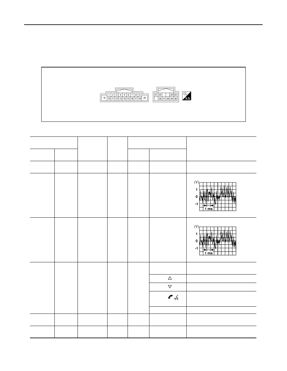
TERMINAL LAYOUT

PHYSICAL VALUES

AWNIA3223ZZ

Terminal

 (Wire color)

Item

Signal in-

put/out-

put

Condition

Reference value (Approx.)

+

Ignition 

switch

Operation

1

 (B/P)

Ground

Amp ON

Output

ON

Battery voltage

2

(W)

3

(B)

Audio signal 
front LH

Output

ON

Receive audio sig-
nal

4

(W/R)

5

(B/R)

Audio signal 
rear LH

Output

ON

Receive audio sig-
nal

(W/G)

Ground

Steering 
switch signal 
A

Input

ON

Depress SOURCE 
switch.

0V

Depress  

switch.

0.7V

Depress  

switch.

1.3V

Depress  


switch.

2.0V

Except for above.

3.3V

7

 (V/Y)

Ground

ACC power

Input

ON

Ignition switch 
ACC or ON

Battery voltage

9

(R/L)

8

(R/Y)

ILL signal

Input

ON

Parking lamps ON

Battery voltage

SKIA0177E

SKIA0177E

AV

AUDIO UNIT

AV-129

< ECU DIAGNOSIS INFORMATION >

[MONOCHROME DISPLAY - W/ BOSE]

C

D

E

F

G

H

I

J

K

L

M

B

A

O

P

11 

(LG)

12

(V)

Audio signal 
front RH

Output

ON

Receive audio sig-
nal

13

(V)

14

(P)

Audio sound 
signal rear RH

Output

ON

Receive audio sig-
nal

15

(L/B)

Steering 
switch ground

16 

(GR/L)

Ground

Steering 
switch signal 
B

Input

ON

Depress volume 
DOWN switch.

0.7V

Depress volume 
UP switch.

1.3V

Depress  


switch.

2.0V

Except for above.

3.3V

18

(V/W)

Ground

Speed signal

Input

ON

When vehicle 

speed is approx 40 

km/hr (25 mph)

19

(Y/R)

Ground

Battery power

Input

Battery voltage

21

(G)

22

(R)

Multimedia 
CAN

Input

23 

(W/b)

Ground

Steering 
switch signal 
A

Output

ON

Depress volume 
DOWN switch.

0.7V

Depress volume 
UP switch.

1.3V

Depress  


switch.

2.0V

Except for above.

3.3V

Terminal

 (Wire color)

Item

Signal in-

put/out-

put

Condition

Reference value (Approx.)

+

Ignition 

switch

Operation

SKIA0177E

SKIA0177E

SKIA6649J

AV-130

< ECU DIAGNOSIS INFORMATION >

[MONOCHROME DISPLAY - W/ BOSE]

AUDIO UNIT

24 

(GR/R)

Ground

Steering 
switch signal 
B

Output

ON

Depress SOURCE 
switch.

0V

Depress  

switch.

0.7V

Depress  

switch.

1.3V

Depress  


switch.

2.0V

Except for above.

3.3V

26

Shield

27

(BR)

28

(Y)

Tel Voice sig-
nal

Input

ON

With Bluetooth

®


transmitting tel-

voice signals to the 

audio unit.

29

(G/O)

Ground

Telephone ON

Output

ON

30

(LG/B)

Shield

Terminal

 (Wire color)

Item

Signal in-

put/out-

put

Condition

Reference value (Approx.)

+

Ignition 

switch

Operation

SKIB3609E

AV

DISPLAY UNIT

AV-131

< ECU DIAGNOSIS INFORMATION >

[MONOCHROME DISPLAY - W/ BOSE]

C

D

E

F

G

H

I

J

K

L

M

B

A

O

P

DISPLAY UNIT

Reference Values

INFOID:0000000009471250

TERMINAL LAYOUT

PHYSICAL VALUES

ALNIA1164ZZ

Terminal

(Wire color)

Description

Condition

Reference value

(Approx.)

+

Signal name

Input/

Output

Ignition 

switch

Operation

1

(G)

Ground M-CAN L

2

(R)

Ground M-CAN H

3

(B)

Ground Ground

Input

ACC

0V

8

(V/Y)

Ground ACC power

Input

ACC

Battery voltage

9

(Y/R)

Ground Battery power

Input

OFF

Battery voltage

10

(R/L)

11

(R/Y)

Illumination

Input

With parking lights ON

Battery voltage


Content   ..  75  76  77  78   ..