Nissan Maxima. Manual - part 73
AV-112
< DTC/CIRCUIT DIAGNOSIS >
[MONOCHROME DISPLAY - W/ BOSE]
TWEETER
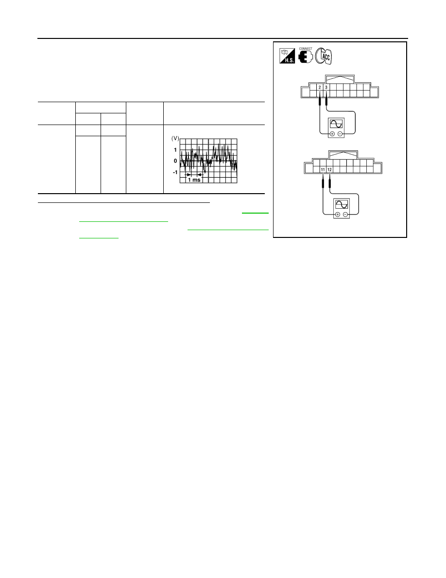
1. Connect audio unit connector and BOSE speaker amp. connec-
tor.
2. Turn ignition switch ACC.
3. Push POWER switch.
4. Check the signal between audio unit harness connector termi-
nals with CONSULT or oscilloscope.
Are the audio signal voltage readings as specified?
YES
>> Replace BOSE speaker amp. Refer to
.
NO
>> Replace audio unit. Refer to
Connector
Terminals
Condition
Reference
signal
(+)
(-)
M132
2
3
Receive
audio sig-
nal
11
12
ALNIA0171ZZ
SKIA0177E