Nissan Maxima. Manual - part 43
ADP-164
< SYMPTOM DIAGNOSIS >
ADP SYSTEM SYMPTOMS
SYMPTOM DIAGNOSIS
ADP SYSTEM SYMPTOMS
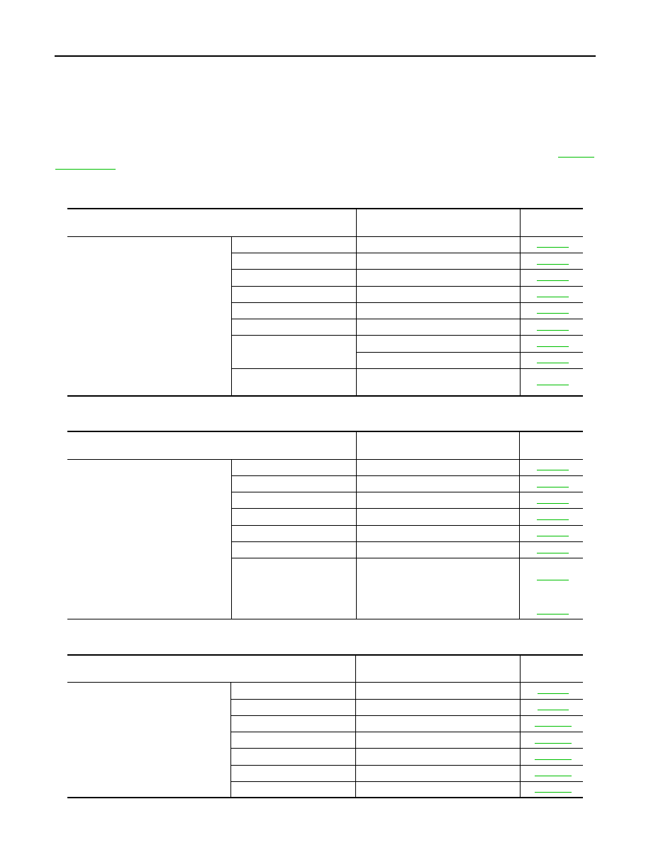
Symptom Table
INFOID:0000000010051834
NOTE:
Always perform the “Basic Inspection” before performing diagnosis in the following table. Refer to
.
SYMPTOM 1
SYMPTOM 2
SYMPTOM 3
Symptom
Diagnosis procedure
Reference
page
Manual functions (for specific part) do
not operate
Sliding operation
Check sliding switch.
Reclining operation
Check reclining switch.
Lifting operation (front)
Check lifting switch (front).
Lifting operation (rear)
Check lifting switch (rear).
Tilt operation
Check tilt switch.
Telescopic sensor
Check telescopic switch.
Door mirror operation
1. Changeover switch.
2. Mirror switch
All parts of seat
Check power seat switch ground cir-
cuit.
Symptom
Diagnosis procedure
Reference
page
Memory functions (for specific part) do
not operate
Sliding operation
Check sliding sensor.
Reclining operation
Check reclining sensor.
Lifting operation (front)
Check lifting sensor (front).
Lifting operation (rear)
Check lifting sensor (rear).
Tilt operation
Check tilt sensor.
Telescopic operation
Check telescopic sensor.
Door mirror operation
Check door mirror sensor.
Driver side:
Passenger
side:
Symptom
Diagnosis procedure
Reference
page
Memory functions and manual func-
tions (for specific part) do not operate
Sliding operation
Check sliding motor.
Reclining operation
Check reclining motor.
Lifting operation (front)
Check lifting motor (front).
Lifting operation (rear)
Check lifting motor (rear).
Tilt operation
Check tilt motor.
Telescopic operation
Check telescopic motor.
Door mirror operation
Check door mirror motor.