Nissan Maxima. Manual - part 29
ADP-108
< DTC/CIRCUIT DIAGNOSIS >
TELESCOPIC MOTOR
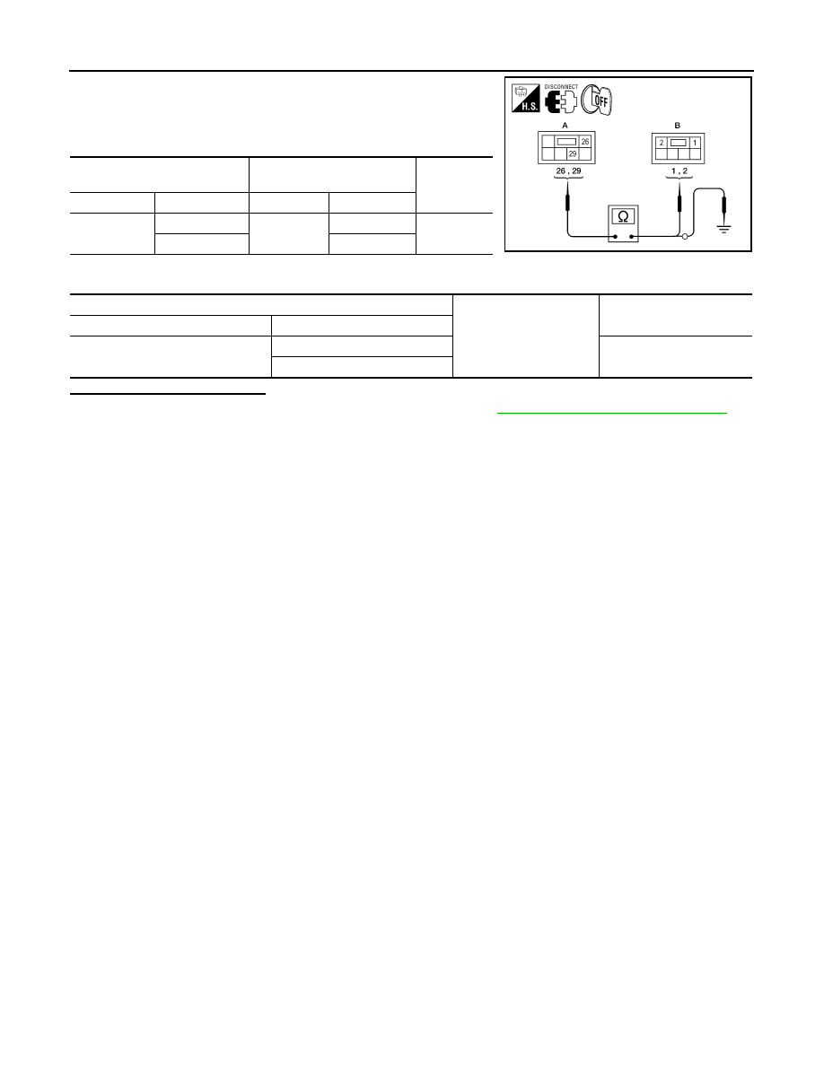
1. Turn ignition switch OFF.
2. Disconnect automatic drive positioner control unit.
3. Check continuity between automatic drive positioner control unit
harness connector and telescopic motor harness connector.
4. Check continuity between automatic drive positioner control unit harness connector and ground.
Is the inspection result normal?
YES
>> Replace automatic drive positioner control unit. Refer to
ADP-170, "Removal and Installation"
NO
>> Repair or replace harness.
Automatic drive positioner control
unit
Telescopic motor
Continuity
Connector
Terminal
Connector
Terminal
M67 (A)
29
M73 (B)
2
Yes
26
1
ALJIA0444ZZ
Automatic drive positioner control unit
Ground
Continuity
Connector
Terminal
M67 (A)
29
No
26