Nissan Maxima. Manual - part 25


  Index      Nissan     Nissan Maxima (2009-2014 year) - Service and Repair Manual


Search            


Content   ..  23  24  25  26   ..


Nissan Maxima. Manual - part 25


ADP-92

< DTC/CIRCUIT DIAGNOSIS >

MIRROR SENSOR

MIRROR SENSOR

DRIVER SIDE
DRIVER SIDE : Description

INFOID:0000000010051791

• The mirror sensor LH is installed to the door mirror LH.

• The resistance of 2 sensors (horizontal and vertical) is changed when the door mirror LH is operated.

• Automatic drive positioner control unit calculates the door mirror position according to the change of the volt-

age of 2 sensor input terminals.

DRIVER SIDE : Component Function Check

INFOID:0000000010051792

1.

 CHECK FUNCTION

1. Select “MIR/SEN LH U-D”, “MIR/SEN LH R-L” in “DATA MONITOR” with CONSULT.

2. Check mirror sensor (driver side) signal under the following condition.

Is the indication normal?

YES

>> Inspection End.

NO

>> Perform diagnosis procedure. Refer to 

ADP-92, "DRIVER SIDE : Diagnosis Procedure"

.

DRIVER SIDE : Diagnosis Procedure

INFOID:0000000010051793

Regarding Wiring Diagram information, refer to 

ADP-150, "Wiring Diagram"

.

1.

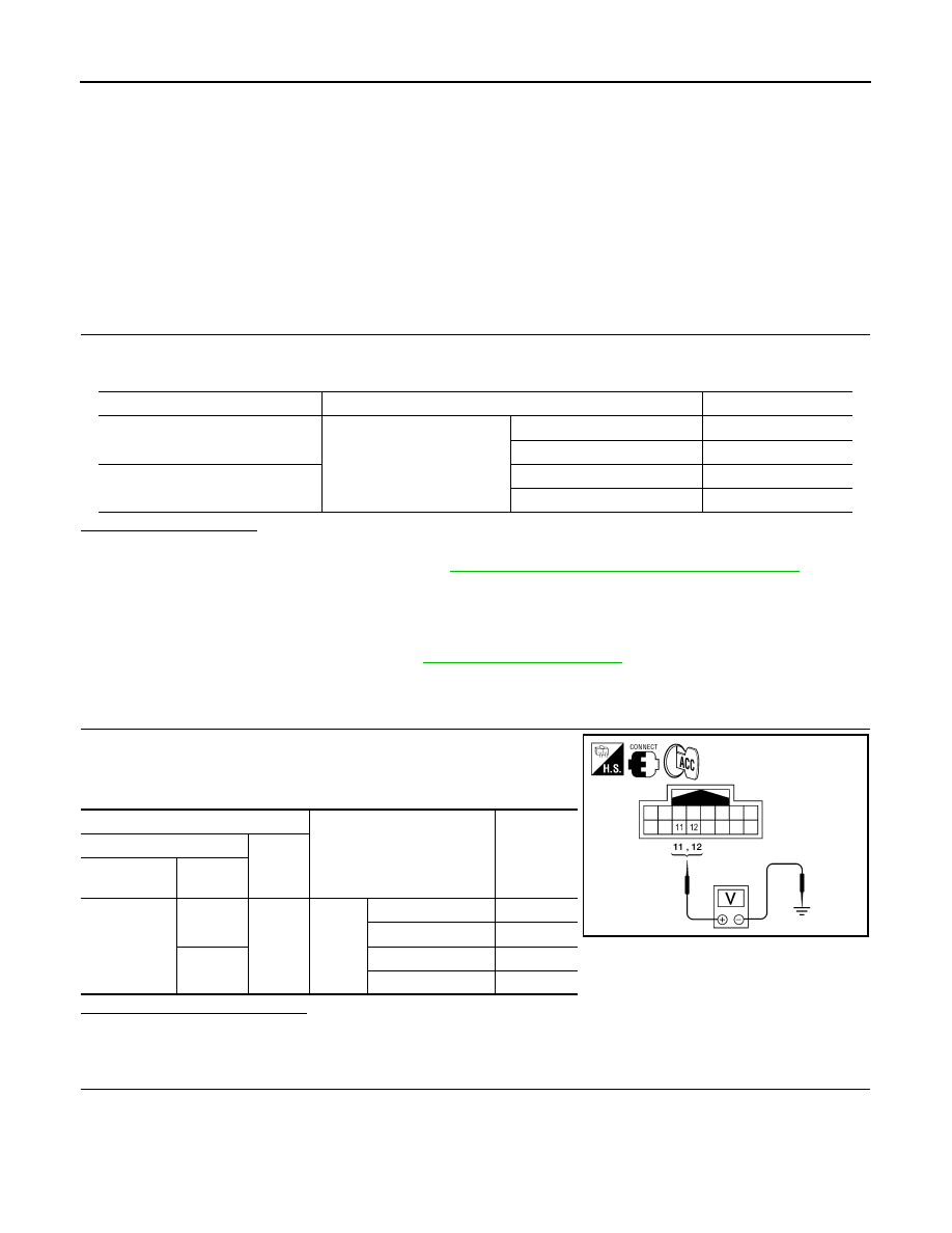
 CHECK DOOR MIRROR LH SENSOR SIGNAL

1. Turn ignition switch to ACC.

2. Check voltage between door mirror LH harness connector and

ground.

Is the inspection result normal?

YES

>> GO TO 5

NO

>> GO TO 2

2.

 CHECK DOOR MIRROR LH SENSOR CIRCUIT 1

Monitor item

Condition

Value

MIR/SEN LH U-D

Door mirror LH

Close to peak

3.4V

Close to valley

0.6V

MIR/SEN LH R-L

Close to right edge

3.4V

Close to left edge

0.6V

Terminals

Condition

Voltage (V)

(Approx.)

(+)

(–)

Door mirror 

LH connector

Terminal

D4

12

Ground

Door 
mirror
LH

Close to peak

3.4

Close to valley

0.6

11

Close to right edge

3.4

Close to left edge

0.6

ALJIA0430ZZ

MIRROR SENSOR

ADP-93

< DTC/CIRCUIT DIAGNOSIS >

C

D

E

F

G

H

I

K

L

M

A

B

ADP

N

O

P

1. Turn ignition switch OFF.

2. Disconnect automatic drive positioner control unit and door mir-

ror LH connector.

3. Check continuity between automatic drive positioner control unit

harness connector and door mirror LH harness connector.

4. Check continuity between automatic drive positioner control unit harness connector and ground.

Is the inspection result normal?

YES

>> GO TO 3

NO

>> Repair or replace harness.

3.

 CHECK DOOR MIRROR LH SENSOR CIRCUIT 2 

1. Check continuity between automatic drive positioner control unit

harness connector and door mirror LH harness connector.

2. Check continuity between automatic drive positioner control unit

harness connector and ground.

Is the inspection result normal?

YES

>> GO TO 4

NO

>> Repair or replace harness.

4.

 CHECK TILT MOTOR ADJUSTING OPERATION

1. Connect automatic drive positioner control unit and door mirror LH.

2. Turn ignition switch ON.

3. Check tilt motor adjusting operation with memory function.
Is the operation normal?

YES

>> Replace door mirror actuator. (Built in door mirror LH). Refer to 

MIR-19, "Removal and Installa-

tion"

.

NO

>> Replace automatic drive positioner control unit. Refer to 

ADP-170, "Removal and Installation"

.

5.

 CHECK INTERMITTENT INCIDENT

Refer to 

GI-41, "Intermittent Incident"

.

Is the inspection result normal?

YES

>> Replace automatic drive positioner control unit. Refer to 

ADP-170, "Removal and Installation"

.

Automatic drive 

positioner control 

unit connector

Terminal

Door mirror LH 

connector

Terminal

Continuity

M63 (A)

6

D4 (B)

12

Yes

18

11

ALJIA0431ZZ

Automatic drive positioner

 control unit connector

Terminal

Ground

Continuity 

M63 (A)

6

No

18

Automatic drive 

positioner control 

unit connector

Terminal

Door mirror LH 

connector

Terminal

Continuity

M63 (A)

20

D4 (B)

9

Yes

21

10

ALJIA0432ZZ

Automatic drive positioner

 control unit connector

Terminal

Ground

Continuity 

M63 (A)

20

No

21

ADP-94

< DTC/CIRCUIT DIAGNOSIS >

MIRROR SENSOR

NO

>> Repair or replace the malfunctioning part.

PASSENGER SIDE
PASSENGER SIDE : Description

INFOID:0000000010051794

• The mirror sensor RH is installed to the door mirror RH.

• The resistance of 2 sensors (horizontal and vertical) is changed when the door mirror RH is operated.

• Automatic drive positioner control unit calculates the door mirror position according to the change of the volt-

age of 2 sensor input terminals.

PASSENGER SIDE : Component Function Check

INFOID:0000000010051795

1.

 CHECK FUNCTION

1. Select “MIR/SEN RH U-D”, “MIR/SEN RH R-L” in “DATA MONITOR” with CONSUL.

2. Check the mirror sensor RH signal under the following conditions.

Is the indication normal?

YES

>> Inspection End.

NO

>> Perform diagnosis procedure. Refer to 

ADP-94, "PASSENGER SIDE : Diagnosis Procedure"

.

PASSENGER SIDE : Diagnosis Procedure

INFOID:0000000010051796

Regarding Wiring Diagram information, refer to 

ADP-150, "Wiring Diagram"

.

1.

 CHECK DOOR MIRROR RH SENSOR SIGNAL

1. Turn ignition switch to ACC.

2. Check voltage between door mirror RH harness connector and

ground.

Is the inspection result normal?

YES

>> GO TO 5

NO

>> GO TO 2

2.

 CHECK DOOR MIRROR RH SENSOR CIRCUIT 1

Monitor item

Condition

Value

MIR/SEN RH U-D

Door mirror RH

Close to peak

3.4V

Close to valley

0.6V

MIR/SEN RH R-L

Close to right edge

3.4V

Close to left edge

0.6V

Terminals

Condition

Voltage (V)

(Approx.)

(+)

(–)

Door mirror 

RH con-

nector

Terminal

D107

12

Ground

Door mirror 
RH

Close to peak

3.4

Close to valley

0.6

11

Close to right edge

3.4

Close to left edge

0.6

ALJIA0430ZZ

MIRROR SENSOR

ADP-95

< DTC/CIRCUIT DIAGNOSIS >

C

D

E

F

G

H

I

K

L

M

A

B

ADP

N

O

P

1. Turn ignition switch OFF.

2. Disconnect automatic drive positioner control unit and door mir-

ror RH.

3. Check continuity between automatic drive positioner control unit

harness connector and door mirror RH harness connector.

4. Check continuity between automatic drive positioner control unit harness connector and ground.

Is the inspection result normal?

YES

>> GO TO 3

NO

>> Repair or replace harness.

3.

 CHECK DOOR MIRROR RH SENSOR CIRCUIT 2 

1. Check continuity between automatic drive positioner control unit

harness connector and door mirror RH harness connector.

2. Check continuity between automatic drive positioner control unit

harness connector and ground.

Is the inspection result normal?

YES

>> GO TO 4

NO

>> Repair or replace harness.

4.

 CHECK TILT MOTOR ADJUSTING OPERATION

1. Connect automatic drive positioner control unit and door mirror RH.

2. Turn ignition switch ON.

3. Check tilt motor adjusting operation with memory function.
Is the operation normal?

YES

>> Replace door mirror actuator. (Built in door mirror RH). Refer to 

MIR-19, "Removal and Installa-

tion"

.

NO

>> Replace automatic drive positioner control unit. Refer to 

ADP-170, "Removal and Installation"

.

5.

 CHECK INTERMITTENT INCIDENT

Refer to 

GI-41, "Intermittent Incident"

.

Is the inspection result normal?

YES

>> Replace automatic drive positioner control unit. Refer to 

ADP-170, "Removal and Installation"

.

Automatic drive posi-

tioner control unit 

connector

Terminal

Door mirror RH 

connector

Terminal

Continuity

M63 (A)

5

D107 (B)

12

Yes

17

11

ALJIA0433ZZ

Automatic drive positioner

 control unit connector

Terminal

Ground

Continuity 

M63 (A)

5

No

17

Automatic drive posi-

tioner control unit 

connector

Terminal

Door mirror RH 

connector

Terminal

Continuity

M63 (A)

20

D107 (B)

9

Yes

21

10

ALJIA0432ZZ

Automatic drive positioner

 control unit connector

Terminal

Ground

Continuity 

M63 (A)

20

No

21


Content   ..  23  24  25  26   ..