Nissan Altima HL32 Hybrid. Manual - part 872


  Index      Nissan     Nissan Altima HL32 Hybrid (2009 year) - Service and Repair Manual


Search            


Content   ..  870  871  872  873   ..


Nissan Altima HL32 Hybrid. Manual - part 872


PCS

PRECAUTIONS

PCS-129

< PRECAUTION >

[POWER DISTRIBUTION SYSTEM]

C

D

E

F

G

H

I

J

K

L

B

A

O

P

N

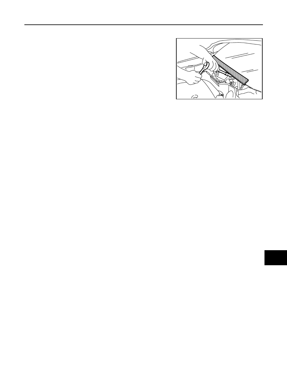
Precaution for Procedure without Cowl Top Cover

INFOID:0000000004533095

When performing the procedure after removing cowl top cover, cover

the lower end of windshield with urethane, etc.

PIIB3706J

PCS-130

< ON-VEHICLE REPAIR >

[POWER DISTRIBUTION SYSTEM]

BCM (BODY CONTROL MODULE)

ON-VEHICLE REPAIR

BCM (BODY CONTROL MODULE)

Removal and Installation

INFOID:0000000004533091

REMOVAL

1. Remove the combination meter. Refer to 

MWI-135, "Removal and Installation"

.

2. Remove the BCM screws (A), and pull out the BCM (1).
3. Disconnect the BCM connector and remove the BCM (1).

INSTALLATION

Installation is the reverse order of removal.

NOTE:

• When replacing BCM, it must be configured. Refer to the CONSULT-III operation manual for the initialization

procedure.

• When replacing BCM, perform initialization of the NATS system and registration of all the intelligent ignition

key IDs. Refer to the CONSULT-III operation manual for the initialization procedure. 

• When replacing BCM, if new BCM does not come with keyfobs attached, all existing keyfobs must be re-reg-

istered.

ALMIA0032ZZ

PG

PG-1

ELECTRICAL & POWER CONTROL

C

D

E

F

G

H

I

J

K

L

B

SECTION 

PG

A

O

P

N

CONTENTS

POWER SUPPLY, GROUND & CIRCUIT ELEMENTS

BASIC INSPECTION  ....................................

2

BATTERY ............................................................

2

How to Handle Battery ..............................................

2

Work Flow  .................................................................

3

Special Repair Requirement .....................................

3

COMPONENT DIAGNOSIS ..........................

4

POWER SUPPLY ROUTING CIRCUIT ...............

4

Wiring Diagram — Battery Power Supply — .............

4

Wiring Diagram — Accessory Power Supply —  .....

12

Wiring Diagram — Ignition Power Supply —  ..........

15

Fuse ........................................................................

23

Fusible Link  .............................................................

23

GROUND ............................................................

24

Ground Distribution  .................................................

24

HARNESS ..........................................................

33

Harness Layout  .......................................................

33

ELECTRICAL UNITS LOCATION ......................

55

Electrical Units Location ..........................................

55

HARNESS CONNECTOR ..................................

59

Description ..............................................................

59

STANDARDIZED RELAY  ..................................

62

Description ..............................................................

62

FUSE BLOCK - JUNCTION BOX (J/B)  .............

64

Terminal Arrangement  ............................................

64

FUSE, FUSIBLE LINK AND RELAY BOX ........

65

Terminal Arrangement .............................................

65

IPDM E/R (INTELLIGENT POWER DISTRI-
BUTION MODULE ENGINE ROOM)  ................

66

Fuse, Connector and Terminal Arrangement  ..........

66

PRECAUTION ..............................................

67

PRECAUTIONS .................................................

67

Supplemental Restraint System SRS "AIR BAG" 
and "SEAT BELT PRE-TENSIONER" Service  ........

67

Precautions For High-Voltage System  ....................

67

Necessary for Steering Wheel Rotation After Bat-
tery Disconnect ........................................................

67

PREPARATION ...........................................

68

PREPARATION .................................................

68

Special Service Tool ................................................

68

Commercial Service Tool  ........................................

68

ON-VEHICLE REPAIR .................................

69

BATTERY ..........................................................

69

Removal and Installation  .........................................

69

SERVICE DATA AND SPECIFICATIONS 
(SDS) ............................................................

70

BATTERY ..........................................................

70

Battery .....................................................................

70

PG-2

< BASIC INSPECTION >

BATTERY

BASIC INSPECTION

BATTERY

How to Handle Battery

INFOID:0000000004495153

WARNING:

These vehicles contain HIGH VOLTAGE SYSTEMS. Service technicians must complete the "2007

Altima Hybrid New Technology Introduction" Service Training before they can service this vehicle.

JUMP-STARTING AN ALTIMA HYBRID WITH A DISCHARGED 12-VOLT BATTERY

CAUTION:

• If it becomes necessary to start the engine with a booster battery and jumper cables, use a 12-volt

booster battery.

• Do not connect the jumper cables to the 12-volt battery

located in the trunk. To jump-start the Altima Hybrid, use the

positive stud and one of the strut mount insulator studs

located in the LH rear of the engine compartment.

NOTE:

Follow all standard safety procedures for typical jump-start of a vehicle.

1. Remove the high voltage fuse and fusible link box cover.

2. Connect the positive (+) jumper cable to the positive stud inside

the fuse box. 

3. Connect the negative (-) jumper cable to one of the strut mount

insulator studs.

4. Confirm the vehicle transmission is in the P (Park) position.

5. Depress the brake pedal and press the "Start Stop" button on

the instrument panel.

6. Confirm the vehicle is in the READY mode. The word READY

will illuminate green in the combination meter.

7. Disconnect the negative (-) jumper cable.

8. Disconnect the positive (+) jumper cable. 

CHARGING AN ALTIMA HYBRID 12-VOLT BATTERY

CAUTION:

• Never “quick charge” the Altima Hybrid 12-volt battery. Use only a trickle charge method.

• Do not attempt to charge the Altima Hybrid 12-volt battery using the positive stud and strut mount

insulator stud as described in the Jump-Starting section of this manual.

• Do not attempt to charge the Altima Hybrid 12-volt battery through the RH inner trunk access panel.

The RH trunk side finisher MUST BE REMOVED prior to charging. 

• When connecting the charger, connect the leads first, then turn on the charger. Never turn on the

charger first, as this may cause a spark.

1. Remove the trunk side finisher (RH). Refer to 

INT-27, "Removal and Installation"

.

2. Confirm the trunk lid is completely open.

3. Confirm all vehicle doors are closed.

4. Disconnect the negative (-) battery cable from the 12-volt battery.

5. Connect the positive (+) charging cable to the positive battery terminal.

6. Connect the negative (-) charging cable to the negative battery terminal.

7. Trickle charge the battery at a low setting (less than 5 amps).

NOTE:

AWMIA0976ZZ

AWMIA0976ZZ


Content   ..  870  871  872  873   ..