Nissan Altima HL32 Hybrid. Manual - part 858


  Index      Nissan     Nissan Altima HL32 Hybrid (2009 year) - Service and Repair Manual


Search            


Content   ..  856  857  858  859   ..


Nissan Altima HL32 Hybrid. Manual - part 858


PCS

PUSH-BUTTON IGNITION SWITCH POSITION INDICATOR

PCS-73

< COMPONENT DIAGNOSIS >

[POWER DISTRIBUTION SYSTEM]

C

D

E

F

G

H

I

J

K

L

B

A

O

P

N

PUSH-BUTTON IGNITION SWITCH POSITION INDICATOR

Description

INFOID:0000000004219172

The switch that changes the power supply position.

BCM maintains the power supply position status.

BCM changes the power supply position with the operation of the push-button ignition switch.

Component Function Check

INFOID:0000000004219173

1.

 CHECK FUNCTION

With CONSULT-III

1. Check push-button ignition switch (“LOCK INDICATOR”,“ACC INDICATOR” and “IGNITION ON IND”) in

Active Test Mode with CONSULT-III.

Is the inspection result normal?

YES

>> Inspection End.

NO

>> Refer to 

PCS-73, "Diagnosis Procedure"

.

Diagnosis Procedure

INFOID:0000000004219174

1.

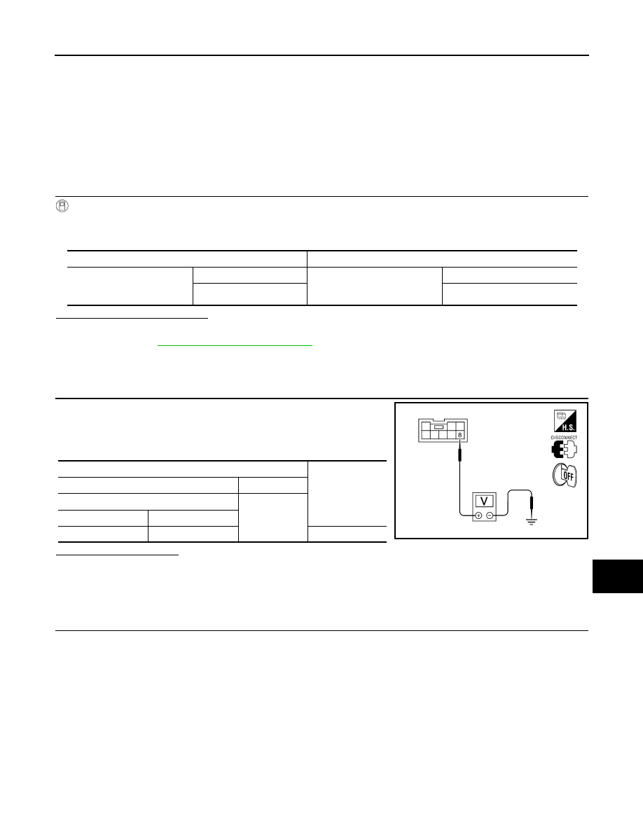
 CHECK PUSH-BUTTON IGNITION SWITCH INPUT SIGNAL

1. Turn ignition switch OFF.

2. Disconnect push-button ignition switch.

3. Check voltage between push-button ignition switch harness con-

nector and ground.

Is the inspection normal?

YES

>> GO TO 2

NO

>> Check the following.

• 10A fuse [No. 9, located in fuse block (J/B)]

• Harness for open or short between push-button ignition switch and fuse.

2.

 CHECK PUSH-BUTTON IGNITION SWITCH CIRCUIT

Test item

Description

LOCK INDICATOR
ACC INDICATOR
IGNITION ON IND

ON

Position indicator

: Illuminate

OFF

: Not illuminate

Terminals

Voltage (V)

(+)

(-)

Push-button ignition switch

Ground

Connector

Terminal

E38

8

Battery voltage

ALMIA0096ZZ

PCS-74

< COMPONENT DIAGNOSIS >

[POWER DISTRIBUTION SYSTEM]

PUSH-BUTTON IGNITION SWITCH POSITION INDICATOR

1. Disconnect BCM and push-button ignition switch.

2. Check continuity between BCM harness connector and push-

button ignition switch harness connector.

3. Check continuity between BCM harness connector and ground.

Is the inspection normal?

YES

>> GO TO 3

NO

>> Repair or replace harness.

3.

 CHECK PUSH-BUTTON IGNITION SWITCH

Refer to 

PCS-75, "Component Inspection"

.

Is the inspection normal?

YES

>> GO TO 4

NO

>> Replace push-button ignition switch. Refer to 

SEC-176, "Removal and Installation"

.

4.

 CHECK INTERMITTENT INCIDENT

Refer to 

GI-42, "Intermittent Incident"

.

>> Inspection End.

Indicator

 BCM Con-

nector

Terminal

 Push-button ignition 

switch connector

Terminal

Continuity

LOCK

M18 (A)

42

E38 (D)

5

Yes

ACC

M17 (B)

15

6

ON

M19 (C)

81

7

ALMIA0097ZZ

Indicator

BCM connector

Terminal

Ground

Continuity

LOCK

M18 (A)

42

No

ACC

M17 (B)

15

ON

M19 (C)

81

ALMIA0098ZZ

PCS

PUSH-BUTTON IGNITION SWITCH POSITION INDICATOR

PCS-75

< COMPONENT DIAGNOSIS >

[POWER DISTRIBUTION SYSTEM]

C

D

E

F

G

H

I

J

K

L

B

A

O

P

N

Component Inspection

INFOID:0000000004219175

1.

 CHECK PUSH-BUTTON IGNITION SWITCH 

Check push-button ignition switch.

Is the inspection result normal?

YES

>> Inspection End.

NO

>> Replace push-button ignition switch. Refer to 

SEC-176,

"Removal and Installation"

.

Terminal

Push-button ignition switch 

position

Continuity

Push-button ignition switch

8

5

LOCK

Yes

6

ACC

7

ON

ALMIA0099ZZ

PCS-76

< ECU DIAGNOSIS >

[POWER DISTRIBUTION SYSTEM]

BCM (BODY CONTROL MODULE)

ECU DIAGNOSIS

BCM (BODY CONTROL MODULE)

Reference Value

INFOID:0000000004498313

VALUES ON THE DIAGNOSIS TOOL

Monitor Item

Condition

Value/Status

FR WIPER HI

Other than front wiper switch HI

OFF

Front wiper switch HI

ON

FR WIPER LOW

Other than front wiper switch LO

OFF

Front wiper switch LO

ON

FR WASHER SW

Front washer switch OFF

OFF

Front washer switch ON

ON

FR WIPER INT

Other than front wiper switch INT

OFF

Front wiper switch INT

ON

FR WIPER STOP

Front wiper is not in STOP position

OFF

Front wiper is in STOP position

ON

INT VOLUME

Wiper intermittent dial is in a dial position 1 - 7

Wiper intermittent dial position

TURN SIGNAL R

Other than turn signal switch RH

OFF

Turn signal switch RH

ON

TURN SIGNAL L

Other than turn signal switch LH

OFF

Turn signal switch LH

ON

TAIL LAMP SW

Other than lighting switch 1ST and 2ND

OFF

Lighting switch 1ST or 2ND

ON

HI BEAM SW

Other than lighting switch HI

OFF

Lighting switch HI

ON

HEAD LAMP SW 1

Other than lighting switch 2ND

OFF

Lighting switch 2ND

ON

HEAD LAMP SW 2

Other than lighting switch 2ND

OFF

Lighting switch 2ND

ON

PASSING SW

Other than lighting switch PASS

OFF

Lighting switch PASS

ON

AUTO LIGHT SW

Other than lighting switch AUTO

OFF

Lighting switch AUTO

ON

FR FOG SW

Front fog lamp switch OFF

OFF

Front fog lamp switch ON

ON

DOOR SW-DR

Front door LH closed

OFF

Front door LH opened

ON

DOOR SW-AS

Front door RH closed

OFF

Front door RH opened

ON

DOOR SW-RR

Rear door RH closed

OFF

Rear door RH opened

ON

DOOR SW-RL

Rear door LH closed

OFF

Rear door LH opened

ON


Content   ..  856  857  858  859   ..