Nissan Altima HL32 Hybrid. Manual - part 856


  Index      Nissan     Nissan Altima HL32 Hybrid (2009 year) - Service and Repair Manual


Search            


Content   ..  854  855  856  857   ..


Nissan Altima HL32 Hybrid. Manual - part 856


PCS

B2616 IGNITION RELAY CIRCUIT

PCS-65

< COMPONENT DIAGNOSIS >

[POWER DISTRIBUTION SYSTEM]

C

D

E

F

G

H

I

J

K

L

B

A

O

P

N

Is the inspection result normal?

YES

>> GO TO 6

NO

>> Repair or replace harness.

3.

 CHECK IGNITION RELAY-2 GROUND CIRCUIT

1. Turn ignition switch OFF.

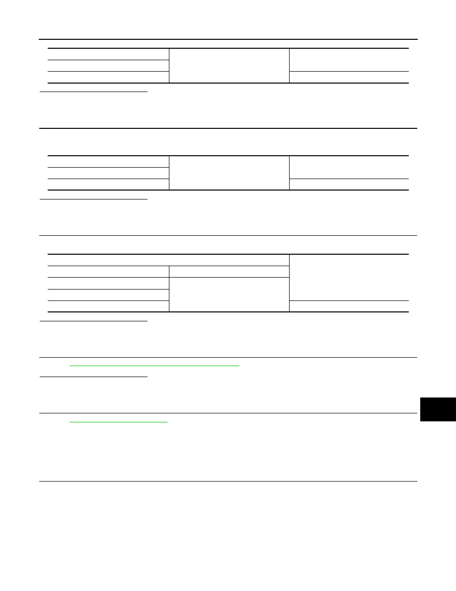
2. Check continuity between ignition relay-2 relay harness connector and ground.

Is the inspection result normal?

YES

>> GO TO 4

NO

>> Repair or replace harness.

4.

 CHECK IGNITION RELAY-2 POWER SUPPLY CIRCUIT-2

Check voltage between ignition relay-2 harness connector and ground.

Is the inspection result normal?

YES

>> GO TO 5

NO

>> Repair or replace harness.

5.

 CHECK IGNITION RELAY-2

Refer to 

PCS-65, "Component Inspection (Ignition Relay)"

.

Is the inspection result normal?

YES

>> GO TO 6

NO

>> Replace ignition relay-2.

6.

 CHECK INTERMITTENT INCIDENT

Refer to 

GI-42, "Intermittent Incident"

.

>> Inspection End.

Component Inspection (Ignition Relay)

INFOID:0000000004219162

1.

 CHECK IGNITION RELAY-2

1. Turn ignition switch OFF.

2. Remove ignition relay-2.

Ignition relay-2

Ground

Continuity

Terminal

2

No

Ignition relay-2

Ground

Continuity

Terminal

1

Yes

Terminals

Voltage (V)

(+)

(-)

Ignition relay-2

Ground

Terminal

5

Battery voltage

PCS-66

< COMPONENT DIAGNOSIS >

[POWER DISTRIBUTION SYSTEM]

B2616 IGNITION RELAY CIRCUIT

3. Check the continuity between ignition relay-2 terminals under

the following conditions.

Is the inspection result normal?

YES

>> Inspection End.

NO

>> Replace ignition relay-2.

Terminals

Condition

Continuity

3 and 5

12V direct current supply between terminals 1 and 2

Yes

No current supply

No

PBIB0098E

PCS

B2618 BCM

PCS-67

< COMPONENT DIAGNOSIS >

[POWER DISTRIBUTION SYSTEM]

C

D

E

F

G

H

I

J

K

L

B

A

O

P

N

B2618 BCM

Description

INFOID:0000000004219163

BCM controls the various electrical components and simultaneously supplies power according to the power

supply position.

BCM checks the power supply position internally.

DTC Logic

INFOID:0000000004219164

DTC DETECTION LOGIC

NOTE:

• If DTC B2618 is displayed with DTC U1000, first perform the trouble diagnosis for DTC U1000. Refer to

PCS-51, "DTC Logic"

.

• If DTC B2618 is displayed with DTC U1010, first perform the trouble diagnosis for DTC U1010. Refer to

PCS-52, "DTC Logic"

.

DTC CONFIRMATION PROCEDURE

1.

 PERFORM DTC CONFIRMATION PROCEDURE

1. Turn ignition switch ON under the following conditions, and wait for at least 1 second.

-

CVT selector lever is in the P or N position

-

Release brake pedal

2. Check “SELF-DIAG RESULTS” with CONSULT-III. 
Is DTC detected?

YES

>> Refer to 

PCS-67, "Diagnosis Procedure"

.

NO

>> Inspection End.

Diagnosis Procedure

INFOID:0000000004219165

1.

 INSPECTION START

1. Turn ignition switch ON.

2. Select “SELF-DIAG RESULTS” mode with CONSULT-III.

3. Touch “ERASE”.

4. Perform DTC Confirmation Procedure.

See 

PCS-67, "DTC Logic"

.

Is the 1st trip DTC B2618 displayed again?

YES

>> Replace BCM. Refer to 

BCS-87, "Removal and Installation"

.

NO

>> Inspection End.

DTC No.

Trouble diagnosis 

name

DTC detecting condition

Possible cause

B2618

BCM

An immediate operation of ignition relay (IPDM E/
R) is requested by BCM, but there is no response 
for more than 1 second

• BCM

PCS-68

< COMPONENT DIAGNOSIS >

[POWER DISTRIBUTION SYSTEM]

B261A PUSH-BUTTON IGNITION SWITCH

B261A PUSH-BUTTON IGNITION SWITCH

Description

INFOID:0000000004219166

BCM transmits the change in the power supply position with the push-button ignition switch to IPDM E/R via

the CAN communication line. IPDM E/R transmits the power supply position status via CAN communication

line to BCM.

DTC Logic

INFOID:0000000004219167

DTC DETECTION LOGIC

DTC CONFIRMATION PROCEDURE

1.

 PERFORM DTC CONFIRMATION PROCEDURE

1. Press the push-button ignition switch under the following conditions, and wait for at least 1 second.

-

CVT selector lever is in the P or N position.

-

Release the brake pedal.

2. Check “SELF-DIAG RESULTS” with CONSULT-III. 
Is DTC detected?

YES

>> Refer to 

PCS-68, "Diagnosis Procedure"

.

NO

>> Inspection End.

Diagnosis Procedure

INFOID:0000000004219168

1.

 CHECK PUSH-BUTTON IGNITION SWITCH OPERATION

Press push-button ignition switch and check if it turns to ON.
Does ignition switch turn to ON?

YES

>> GO TO 2

NO

>> GO TO 4

2.

 CHECK IGNITION SWITCH OUTPUT SIGNAL (IPDM E/R)

1. Disconnect push-button ignition switch.

2. Check voltage between IPDM E/R harness connector and

ground.

Is the inspection result normal?

YES

>> GO TO 3

NO

>> Replace IPDM E/R. Refer to 

PCS-39, "Removal and Installation"

.

3.

 CHECK PUSH-BUTTON IGNITION SWITCH CIRCUIT (IPDM E/R)

DTC No.

Trouble diagnosis 

name

DTC detecting condition

Possible cause

B261A

PUSH-BUTTON IG-
NITION SWITCH

 BCM detects a difference of signal for 1 second or 
more between the following information. 
• Power supply position by push-button ignition 

switch

• Power supply position from IPDM E/R (CAN)

• Harness or connectors

(Push-button ignition switch circuit 
is open or shorted.)

Terminals

Voltage (V)

(+)

(-)

IPDM E/R

Ground

Connector

Terminal

E18

28

Battery voltage

ALMIA0090ZZ


Content   ..  854  855  856  857   ..