Nissan Altima HL32 Hybrid. Manual - part 854


  Index      Nissan     Nissan Altima HL32 Hybrid (2009 year) - Service and Repair Manual


Search            


Content   ..  852  853  854  855   ..


Nissan Altima HL32 Hybrid. Manual - part 854


PCS

B2611 ACC RELAY

PCS-57

< COMPONENT DIAGNOSIS >

[POWER DISTRIBUTION SYSTEM]

C

D

E

F

G

H

I

J

K

L

B

A

O

P

N

Is the inspection result normal?

YES

>> GO TO 3

NO

>> Repair or replace harness.

3.

 CHECK FUSE

Check 10A fuse [No. 19, located in the fuse block (J/B)].
Is the inspection result normal?

YES

>> GO TO 4

NO

>> Replace fuse.

4.

 CHECK ACC RELAY FEEDBACK CIRCUIT

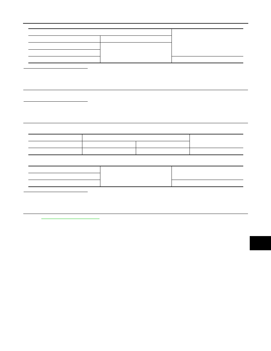
1. Check continuity between ACC relay harness connector and BCM harness connector.

2. Check continuity between ACC relay harness connector and ground.

Is the inspection result normal?

YES

>> GO TO 5

NO

>> Repair or replace harness.

5.

 CHECK INTERMITTENT

Refer to 

GI-42, "Intermittent Incident"

.

>> Inspection End.

Terminals

Voltage (V)

(+)

(-)

ACC relay

Ground

Terminal

5

Battery voltage

ACC relay

BCM

Continuity

Terminal

Connector

Terminal

3

M18

30

Yes

ACC relay

Ground

Continuity

Terminal

3

No

PCS-58

< COMPONENT DIAGNOSIS >

[POWER DISTRIBUTION SYSTEM]

B2614 ACC RELAY CIRCUIT

B2614 ACC RELAY CIRCUIT

Description

INFOID:0000000004219151

BCM controls the various electrical components and simultaneously supplies power according to the power

supply position.

BCM checks the power supply position internally.

DTC Logic

INFOID:0000000004219152

DTC DETECTION LOGIC

DTC CONFIRMATION PROCEDURE

1.

 PERFORM DTC CONFIRMATION PROCEDURE

1. Turn the power supply position to ACC under the following conditions, and wait for at least 1 second.

-

CVT selector lever is in the P or N position.

-

Release the brake pedal.

2. Check “SELF-DIAG RESULTS” with CONSULT-III. 
Is DTC detected?

YES

>> Refer to 

PCS-58, "Diagnosis Procedure"

.

NO

>> Inspection End.

Diagnosis Procedure

INFOID:0000000004219153

1.

 CHECK ACCESSORY RELAY POWER SUPPLY

1. Turn ignition switch OFF.

2. Disconnect accessory relay.

3. Check voltage between accessory relay harness connector and ground under the following conditions.

Is the inspection result normal?

YES

>> GO TO 3

NO

>> GO TO 2

2.

 CHECK ACCESSORY RELAY POWER SUPPLY CIRCUIT

1. Turn ignition switch OFF.

2. Disconnect BCM.

3. Check continuity between accessory relay harness connector and BCM harness connector.

4. Check continuity between accessory relay harness connector and ground.

DTC No.

Trouble diagnosis 

name

DTC detecting condition

Possible cause

B2614

ACC relay circuit

An immediate operation of ACC relay is requested 
by BCM, but there is no response for more than 1 
second.

• Harness or connectors

(ACC relay circuit is open or short-
ed)

• ACC relay

Terminals

Condition

Voltage (V)

(+)

(-)

Accessory relay

Ground

Terminal

2

Ignition

OFF

0

ACC

Battery voltage

Accessory relay

BCM

Continuity

Terminal

Connector

Terminal

2

M19

83

Yes

PCS

B2614 ACC RELAY CIRCUIT

PCS-59

< COMPONENT DIAGNOSIS >

[POWER DISTRIBUTION SYSTEM]

C

D

E

F

G

H

I

J

K

L

B

A

O

P

N

Is the inspection result normal?

YES

>> GO TO 6

NO

>> Repair or replace harness.

3.

 CHECK ACCESSORY RELAY GROUND CIRCUIT

1. Turn ignition switch OFF.

2. Check continuity between accessory relay harness connector and ground.

Is the inspection result normal?

YES

>> GO TO 4

NO

>> Repair or replace harness.

4.

 CHECK ACCESSORY RELAY POWER SUPPLY CIRCUIT-2

Check voltage between accessory relay harness connector and ground.

Is the inspection result normal?

YES

>> GO TO 5

NO

>> Repair or replace harness.

5.

 CHECK ACCESSORY RELAY

Refer to 

PCS-59, "Component Inspection (Accessory Relay)"

.

YES or NO

YES

>> GO TO 6

NO

>> Replace accessory relay.

6.

 CHECK INTERMITTENT INCIDENT

Refer to 

GI-42, "Intermittent Incident"

.

>> Inspection End.

Component Inspection (Accessory Relay)

INFOID:0000000004219154

1.

 CHECK ACCESSORY RELAY

Accessory relay

Ground

Continuity

Terminal

2

No

Accessory relay

Ground

Continuity

Terminal

1

Yes

Terminals

Voltage (V)

(+)

(-)

Accessory relay

Ground

Terminal

3

Battery voltage

PCS-60

< COMPONENT DIAGNOSIS >

[POWER DISTRIBUTION SYSTEM]

B2614 ACC RELAY CIRCUIT

1. Turn ignition switch OFF.

2. Remove accessory relay.

3. Check the continuity between accessory relay terminals under

the following conditions.

Is the inspection result normal?

YES

>> Inspection End.

NO

>> Replace accessory relay.

Terminals

Condition

Continuity

3 and 5

12V direct current supply between terminals 1 and 2

Yes

No current supply

No

PBIB0098E


Content   ..  852  853  854  855   ..