Nissan Altima HL32 Hybrid. Manual - part 790


  Index      Nissan     Nissan Altima HL32 Hybrid (2009 year) - Service and Repair Manual


Search            


Content   ..  788  789  790  791   ..


Nissan Altima HL32 Hybrid. Manual - part 790


LU-12

< ON-VEHICLE REPAIR >

[QR25DE]

OIL PUMP

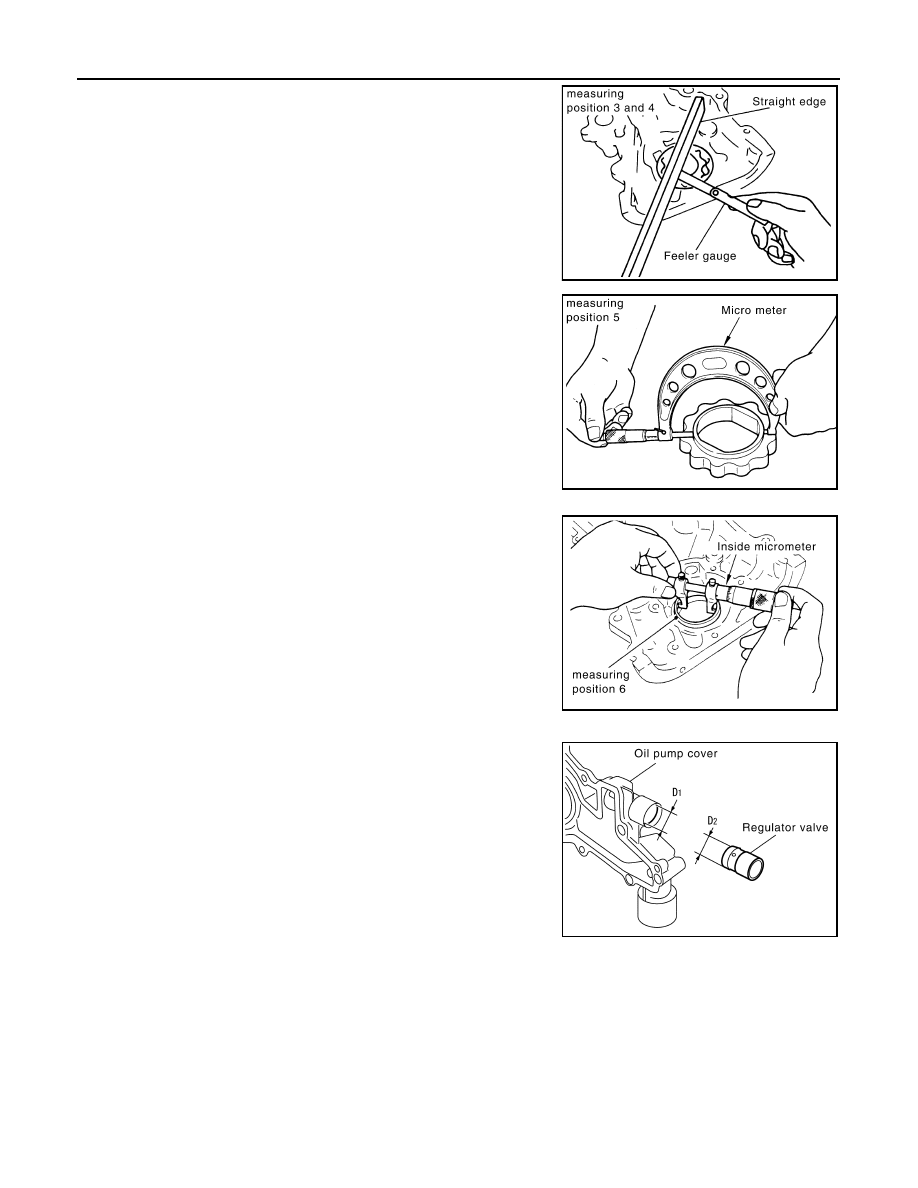
2. Measure clearance with feeler gauge and straightedge as fol-

lows:

• Side clearance between inner rotor and oil pump body (posi-

tion 3).

• Side clearance between outer rotor and oil pump body (posi-

tion 4).

3. Calculate the clearance between inner rotor and oil pump body

as follows:

• Measure the outer diameter of protruded portion of inner rotor

(Position 5).

• Measure the inner diameter of oil pump body with inside

micrometer (Position 6).

• (Clearance) = (Inner diameter of oil pump body) – (Outer

diameter of inner rotor).

4. Calculate regulator valve clearance as follows:

• (Clearance) = D1(Valve hole diameter) – D2 (Outer diameter

of valve)

CAUTION:

Coat regulator valve with engine oil.

Check that it falls smoothly into the valve hole by its own

weight.

ASSEMBLY

Standard

: 0.030 - 0.070 mm (0.0012 - 0.0028 in)

Standard

: 0.060 - 0.110 mm (0.0024 - 0.0043 in)

PBIC0252E

PBIC0253E

Standard

: 0.035 - 0.070 mm (0.0014 - 0.0028 in)

PBIC0254E

Standard

: 0.040 - 0.097 mm (0.0016 - 0.0038 in)

KBIA0043E

OIL PUMP

LU-13

< ON-VEHICLE REPAIR >

[QR25DE]

C

D

E

F

G

H

I

J

K

L

M

A

LU

N

P

O

Assembly is in the reverse order of disassembly.

• Install the inner rotor and outer rotor with the punched marks on

the oil pump cover side.

CAUTION:

Before assembly, apply new engine oil to the parts as specified.

PBIC0255E

LU-14

< ON-VEHICLE REPAIR >

[QR25DE]

OIL COOLER

OIL COOLER

Removal and Installation

INFOID:0000000004211276

WARNING:

Be careful not to get burned when engine coolant and engine oil may be hot.

CAUTION:

• When removing the oil cooler, use a shop cloth to absorb any engine oil leaks or spills.

• Completely wipe off any engine oil that adhere to the engine and the vehicle.

REMOVAL

1. Drain the engine oil. Refer to 

LU-9, "Changing Engine Oil"

.

2. Drain the engine coolant. Refer to 

CO-11, "Changing Engine Coolant"

.

CAUTION:

Do not spill coolant on the drive belt.

3. Disconnect the oil pressure switch connector and remove the oil pressure switch.

CAUTION:

Do not drop or shock the oil pressure switch.

4. Disconnect the water hoses from the oil cooler.

NOTE:

For reference during installation, put matching marks on oil cooler hoses.

5. Remove the oil cooler.

INSPECTION AFTER REMOVAL

1. Check oil cooler for cracks.

1.

Oil pressure switch

2.

Oil cooler

3.

Gasket

4.

Water hose (outlet)

5.

Water hose (inlet)

A.

To water control valve housing

B.

To heater pipe assembly

C.

Hose clamp

D.

Clip

ALBIA0538GB

OIL COOLER

LU-15

< ON-VEHICLE REPAIR >

[QR25DE]

C

D

E

F

G

H

I

J

K

L

M

A

LU

N

P

O

2. Check oil cooler for clogging by blowing through coolant inlet. If necessary, replace oil cooler assembly.

INSTALLATION

Installation is in the reverse order of removal.

• Remove any old liquid gasket adhering to the oil pressure switch and oil cooler before installing the oil pres-

sure switch.

INSPECTION AFTER INSTALLATION

Turn the Hybrid System ON and start engine. Check that there are no engine oil or coolant leaks.


Content   ..  788  789  790  791   ..