Nissan Altima HL32 Hybrid. Manual - part 767
LAN-22
< HOW TO USE THIS MANUAL >
[CAN]
DESCRIPTION
*: For the details, refer to
HBC-80, "Diagnosis Description"
.
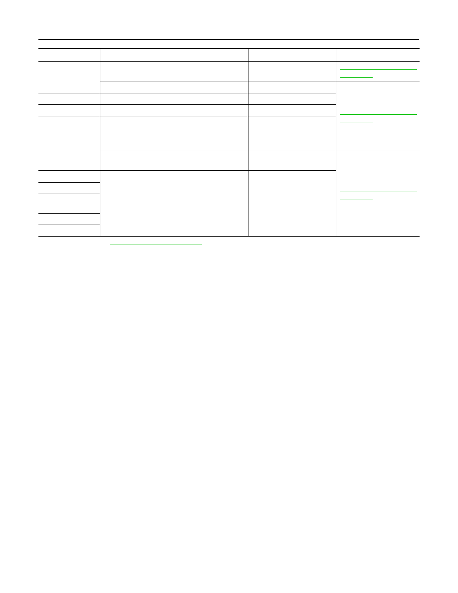
Unit
DTC (INF code
*
) displayed on CONSULT-III
CAN communication system
Inspection
ECM
P0607, U1001, U0164
CAN
LAN-16, "Trouble Diagnosis
Flow Chart"
P0607, U0129, U0293, U1020, U1022
HEV SYSTEM CAN
LAN-53, "Trouble Diagnosis
Flow Chart"
EPS control unit
C1608, U0129, U0293
HEV SYSTEM CAN
Brake ECU
C1300, U0073, U0123, U0124, U0126, U0293
HEV SYSTEM CAN
Hybrid vehicle con-
trol ECU
P0A1D (924), P0A1D (925), U0100, U0100 (211),
U0100 (212), U0100 (530), U0129, U0129 (220),
U0129 (222), U0129 (528), U0131, U0131 (433),
U0131 (434)
HEV SYSTEM CAN
U1001, U1001 (146), U1001 (435), U1001 (594),
U1001 (827), U1001 (919), U1001 (920)
CAN
LAN-16, "Trouble Diagnosis
Flow Chart"
AV control unit
P0607, U1000, U1010
CAN
BCM
Controller (auto
amp.)
Combination meter
IPDM E/R