Nissan Altima HL32 Hybrid. Manual - part 733


  Index      Nissan     Nissan Altima HL32 Hybrid (2009 year) - Service and Repair Manual


Search            


Content   ..  731  732  733  734   ..


Nissan Altima HL32 Hybrid. Manual - part 733


TRUNK ROOM LAMP CIRCUIT

INL-23

< COMPONENT DIAGNOSIS >

C

D

E

F

G

H

I

J

K

M

A

B

INL

N

O

P

YES

>> Check trunk room lamp for an open. If OK, replace BCM. Refer to 

BCS-87, "Removal and Installa-

tion"

. If NG, replace trunk room lamp. Refer to 

INL-88, "Removal and Installation"

.

NO

>> Repair harness or connectors.

3.

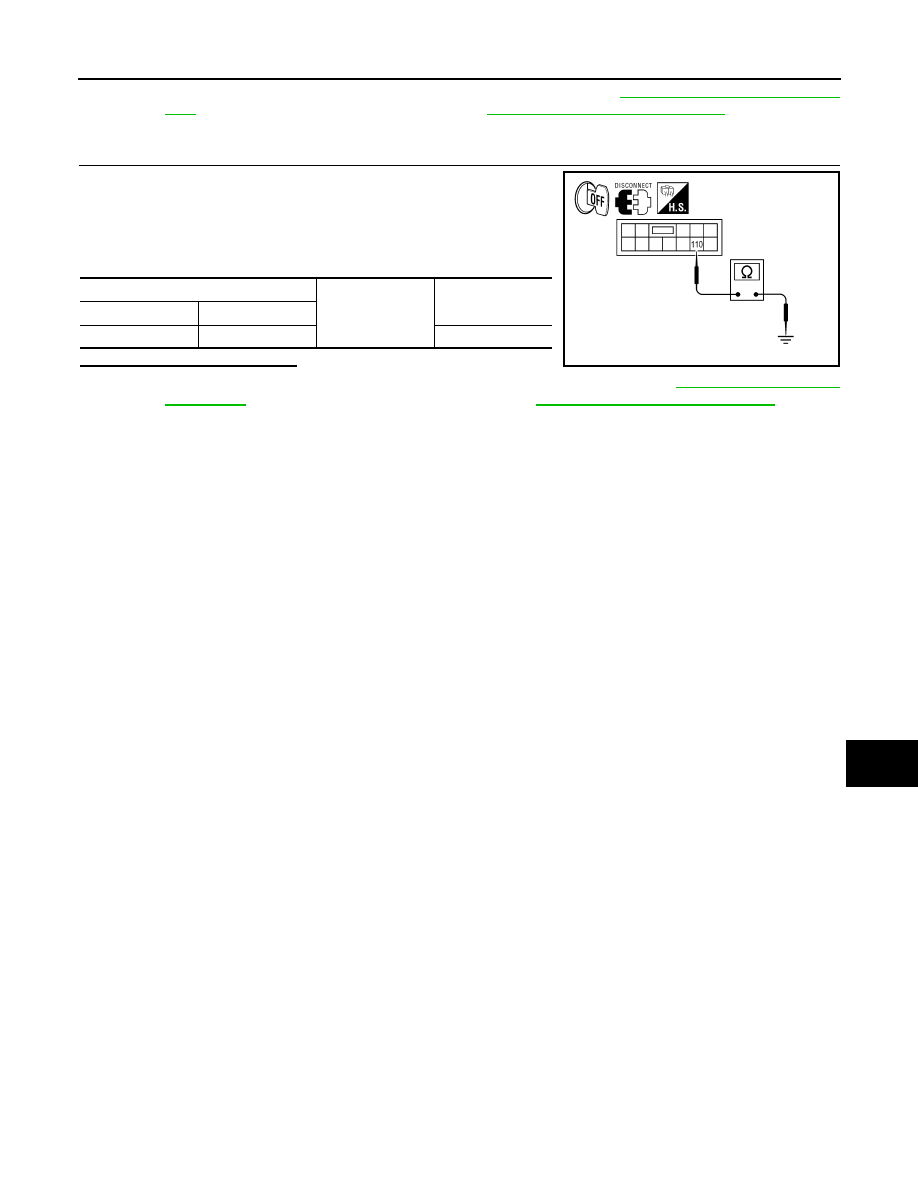
CHECK TRUNK ROOM LAMP SHORT CIRCUIT

1. Turn ignition switch OFF.

2. Disconnect BCM connector M20 and trunk room lamp connec-

tor.

3. Check continuity between BCM harness connector M20 terminal

110 and ground.

Is the inspection result normal?

YES

>> Check trunk room lamp for a short circuit. If OK, replace BCM. Refer to 

BCS-87, "Removal and

Installation"

. If NG, replace trunk room lamp. Refer to 

INL-88, "Removal and Installation"

.

NO

>> Repair harness or connectors.

BCM

Ground

Continuity

Connector

Terminal

M20

110

No

ALLIA0111ZZ

INL-24

< COMPONENT DIAGNOSIS >

PUSH-BUTTON IGNITION SWITCH ILLUMINATION CIRCUIT

PUSH-BUTTON IGNITION SWITCH ILLUMINATION CIRCUIT

Description

INFOID:0000000004216482

Provides the power supply and the ground to control the push-button ignition switch illumination.

Component Function Check

INFOID:0000000004216483

1.

CHECK PUSH-BUTTON IGNITION SWITCH ILLUMINATION OPERATION

CONSULT-III

1. Turn the ignition switch ON.

2. Select “ENGINE SW ILLUMI” of BCM (INTELLGENT KEY) active test item.

3. While operating the test item, check that the push-button ignition switch illumination turns ON/OFF

Is the inspection result normal?

YES

>> Push-button ignition switch illumination circuit is normal.

NO

>> Refer to 

INL-24, "Diagnosis Procedure"

.

Diagnosis Procedure

INFOID:0000000004216484

1.

CHECK PUSH-BUTTON IGNITION SWITCH ILLUMINATION OPERATION

CONSULT-III

1. Turn the ignition switch ON.

2. Select “ENGINE SW ILLUMI” of BCM (INTELLIGENT KEY)

active test item.

3. While operating the test item, check voltage between push-but-

ton ignition switch connector M38 terminal 3 and ground.

Is the inspection result normal?

YES

>> GO TO 4

NO

>> GO TO 2

2.

CHECK PUSH-BUTTON IGNITION SWITCH ILLUMINATION POWER SUPPLY OPEN CIRCUIT

1. Turn the ignition switch OFF.

2. Disconnect BCM connector M18 and push-button ignition switch

connector.

3. Check continuity between BCM connector M18 (A) terminal 41

and push-button ignition switch connector M38 (B) terminal 3.

Is the inspection result normal?

YES

>> GO TO 3

NO

>> Repair the harness or connectors.

ON

: Push-button ignition switch illumination ON

OFF

: Push-button ignition switch illumination OFF

Terminals

Test item

Voltage

(+)

(-)

Push-button ignition switch

Ground

ENGINE SW 

ILLUMI

Connector

Terminal

M38

3

ON

5 V

OFF

0 V

AWLIA1474ZZ

BCM

Push-button ignition switch

Continuity

Connector

Terminal

Connector

Terminal

M18

41

M38

3

Yes

ALLIA0114ZZ

PUSH-BUTTON IGNITION SWITCH ILLUMINATION CIRCUIT

INL-25

< COMPONENT DIAGNOSIS >

C

D

E

F

G

H

I

J

K

M

A

B

INL

N

O

P

3.

CHECK PUSH-BUTTON IGNITION SWITCH ILLUMINATION POWER SUPPLY SHORT CIRCUIT

Check continuity between BCM connector M18 terminal 41 and

ground.

Is the inspection result normal?

YES

>> Replace BCM. Refer to 

BCS-87, "Removal and Installa-

tion"

.

NO

>> Repair the harness or connectors.

4.

CHECK PUSH-BUTTON IGNITION SWITCH ILLUMINATION GROUND CIRCUIT

1. Turn the ignition switch OFF

2. Disconnect push-button ignition switch connector.

3. Check continuity between push-button ignition switch connector

M38 terminal 2 and ground.

Is the inspection result normal?

YES

>> Replace push-button ignition switch.

NO

>> GO TO 5

5.

CHECK PUSH-BUTTON IGNITION SWITCH ILLUMINATION GROUND OPEN CIRCUIT

1. Disconnect BCM connector M17.

2. Check continuity between BCM connector M17 (A) terminal 14

and push-button ignition switch connector M38 (B) terminal 2.

Is the inspection result normal?

YES

>> Replace BCM. Refer to 

BCS-87, "Removal and Installa-

tion"

.

NO

>> Repair the harness or connectors.

BCM

Ground

Continuity

Connector

Terminal

M18

41

No

ALLIA0115ZZ

Push-button ignition switch

Ground

Continuity

Connector

Terminal

M38

2

No

AWLIA1524ZZ

BCM

Push-button ignition switch

Continuity

Connector

Terminal

Connector

Terminal

M17 (A)

14

M38 (B)

2

Yes

ALLIA0112ZZ

INL-26

< COMPONENT DIAGNOSIS >

INTERIOR ROOM LAMP CONTROL SYSTEM

INTERIOR ROOM LAMP CONTROL SYSTEM

Wiring Diagram

INFOID:0000000004216485

ABLWA0242GB


Content   ..  731  732  733  734   ..