Nissan Altima HL32 Hybrid. Manual - part 692


  Index      Nissan     Nissan Altima HL32 Hybrid (2009 year) - Service and Repair Manual


Search            


Content   ..  690  691  692  693   ..


Nissan Altima HL32 Hybrid. Manual - part 692


P3004-131

HBC-517

< COMPONENT DIAGNOSIS >

D

E

F

G

H

I

J

K

L

M

A

B

HBC

N

O

P

DTC Logic

INFOID:0000000004212122

DTC DETECTION LOGIC

Diagnosis Procedure

INFOID:0000000004212123

1.

PRECONDITIONING

• Before inspecting the high-voltage system or disconnecting the low voltage connector of the inverter with

converter assembly, take safety precautions such as wearing insulated gloves and removing the service

plug grip to prevent electrical shocks. After removing the service plug grip, put it in your pocket to prevent

other technicians from accidentally reconnecting it while you are working on the high-voltage system.

• After disconnecting the service plug grip, wait for at least 10 minutes before touching any of the high-voltage

connectors or terminals.
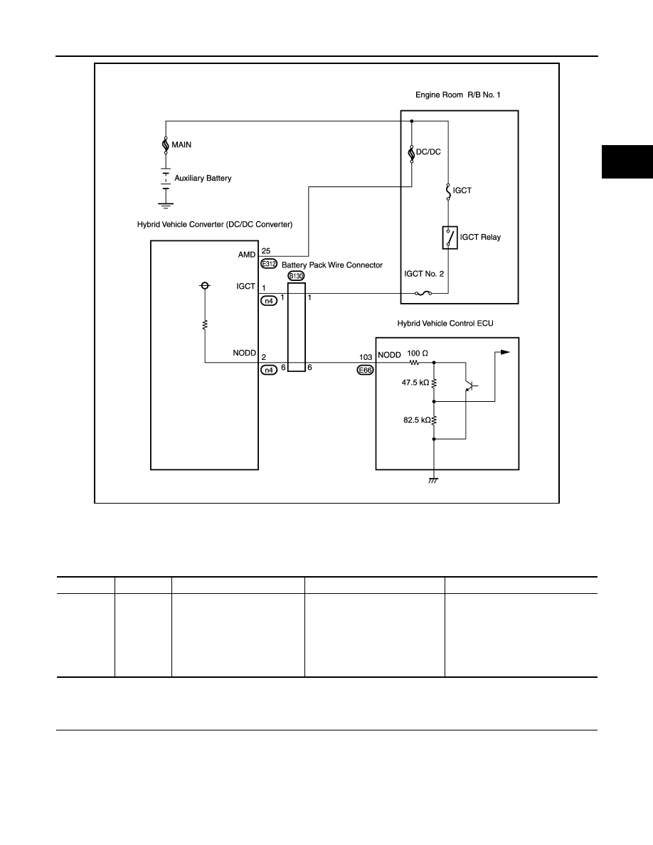
JMCIA0125GB

DTC No.

INF code

Trouble diagnosis name

DTC detecting condition

Possible cause

P3004

131

Power cable malfunction

The inverter voltage is not boost-
ed during precharge (time from 
when SMRP turns on until when 
SMRG turns on).

• HV relay assembly
• Frame wire
• Inverter with converter assembly
• HV battery
• Wire harness or connector
• Hybrid vehicle converter (DC/DC 

converter)

HBC-518

< COMPONENT DIAGNOSIS >

P3004-131

• Waiting for at least 10 minutes is required to discharge the high-voltage capacitor inside the inverter with

converter assembly.

>> GO TO 2.

2.

CHECK DTC OUTPUT (HYBRID SYSTEM)

1. Turn ignition switch ON.

2. Check DTC.

Is DTC detected?

YES

>> Go to Diagnosis Procedure relevant to output DTC.

NO

>> GO TO 3.

3.

CHECK FREEZE FRAME DATA

1. Turn ignition switch ON.

2. Check DTC.

3. Read the freeze frame data for DTC P3004-131.

A or B

A

>> Replace inverter with converter assembly. (See 

HBC-638, "Removal and Installation"

).

B

>> GO  TO  4.

4.

CHECK CONNECTOR CONNECTION CONDITION (HYBRID VEHICLE CONTROL ECU CONNECTOR)

See 

HBC-109, "Diagnosis Procedure"

.

OK or NG

OK

>> GO TO 5.

NG

>> Connect securely.

5.

CHECK CONDITION OF FRAME WIRE CONNECTION(S) (INVERTER WITH CONVERTER ASSEMBLY

SIDE)

CAUTION:

Be sure to wear insulated gloves.

1. Turn ignition switch OFF and remove the service plug grip. (See 

HBC-632, "Precautions for Inspecting the

Hybrid Control System"

)

DTC No.

Related Part

P0A95

Electric vehicle fuse circuit

P0AE7-224, P0AE6-225

SMRP control line circuit

P0ADC-226, P0ADB-227

SMRB control line circuit

P0A1F, P3105, P0AFA

Battery smart unit, VB sensor circuit

P0ABF, P0AC0, P0AC1, P0AC2

IB sensor circuit

P3004-800, 801

High-voltage power source line circuit

P0A1A-156, 658, 151, 155, 659
P0A1B-511, 164, 163, 512, 193, 786, 788, 661
P0A78-266, 267, 523, 586, P0A94-442

VH sensor circuit

Result

Related Part

Inverter voltage (VH) is below 50 V and difference between HV battery voltage 
(PWR RESOURCE VB) and boost converter voltage (VL) is 50 V or less. 

A

Other than above

B

P3004-131

HBC-519

< COMPONENT DIAGNOSIS >

D

E

F

G

H

I

J

K

L

M

A

B

HBC

N

O

P

2. Check the connections between the frame wire and the inverter

with converter assembly.

OK or NG

OK

>> GO TO 6.

NG

>> Connect securely.

6.

CHECK CONDITION OF FRAME WIRE CONNECTION(S) (HV RELAY ASSEMBLY SIDE)

CAUTION:

Be sure to wear insulated gloves.

1. Check that the service plug grip is not installed.

2. Check the connections between the frame wire and the HV relay

assembly.

NOTE:

For the removal and installation procedures related to inspection

of the frame wire connection, (See 

HBB-105, "Removal and

Installation"

).

-

1: Frame wire connector h3 (

−)

-

2: Frame wire connector h4 (+)

OK or NG

OK

>> GO TO 7.

NG

>> Connect securely.

7.

CHECK FRAME WIRE

CAUTION:

Be sure to wear insulated gloves.

1. Check that the service plug grip is not installed.

2. Disconnect the frame wire from the inverter with converter

assembly (See 

HBC-638, "Removal and Installation"

).

3. Disconnect the frame wire from the HV relay assembly (See

HBB-105, "Removal and Installation"

).

4. Measure the resistance according to the value(s) in the table

below.

OK: The connectors are connected securely and 

there are no contact problems.

AWCIA0027ZZ

Torque: 9.0 N*m (92 kgf*cm, 81 in.*lbf)

AWCIA0028ZZ

AWCIA0027ZZ

JMCIA0194GB

HBC-520

< COMPONENT DIAGNOSIS >

P3004-131

OK or NG

OK

>> GO TO 8.

NG

>> Replace frame wire.

8.

CHECK CONNECTOR CONNECTION CONDITION (BATTERY PACK WIRE CONNECTOR)

See 

HBC-140, "Diagnosis Procedure"

.

OK or NG

OK

>> GO TO 9.

NG

>> Connect securely.

9.

CHECK HARNESS AND CONNECTOR (HYBRID VEHICLE CONTROL ECU - BATTERY PACK WIRE

CONNECTOR)
NOTE:

Be sure to wear insulated groves.

1. Check that the service plug grip is not installed.

2. Disconnect the E66 hybrid vehicle control ECU connector.

3. Disconnect the B130 battery pack wire connector (See 

HBB-97,

"Removal and Installation"

).

NOTE:

Due to the time required to disconnect the HV relay assembly

and hybrid vehicle converter (DC/DC converter) connectors, the

battery pack wire resistance check should be performed before

these connectors are disconnected.

-

Battery pack wire connector B130 (1)

JMCIA0195GB

Frame Wire

(Inverter with Converter Assembly Side)

Frame Wire

(HV Relay Assembly Side)

Resistance

Harness connector

Terminal

Harness connector

Terminal

E313

1 (High voltage +)

E308

21 (High voltage +)

Below 1

2 (High voltage –)

E309

22 (High voltage –)

Below 1

AWCIA0020ZZ


Content   ..  690  691  692  693   ..