Nissan Altima HL32 Hybrid. Manual - part 672
P0ADB-227, P0ADC-226
HBC-437
< COMPONENT DIAGNOSIS >
D
E
F
G
H
I
J
K
L
M
A
B
HBC
N
O
P
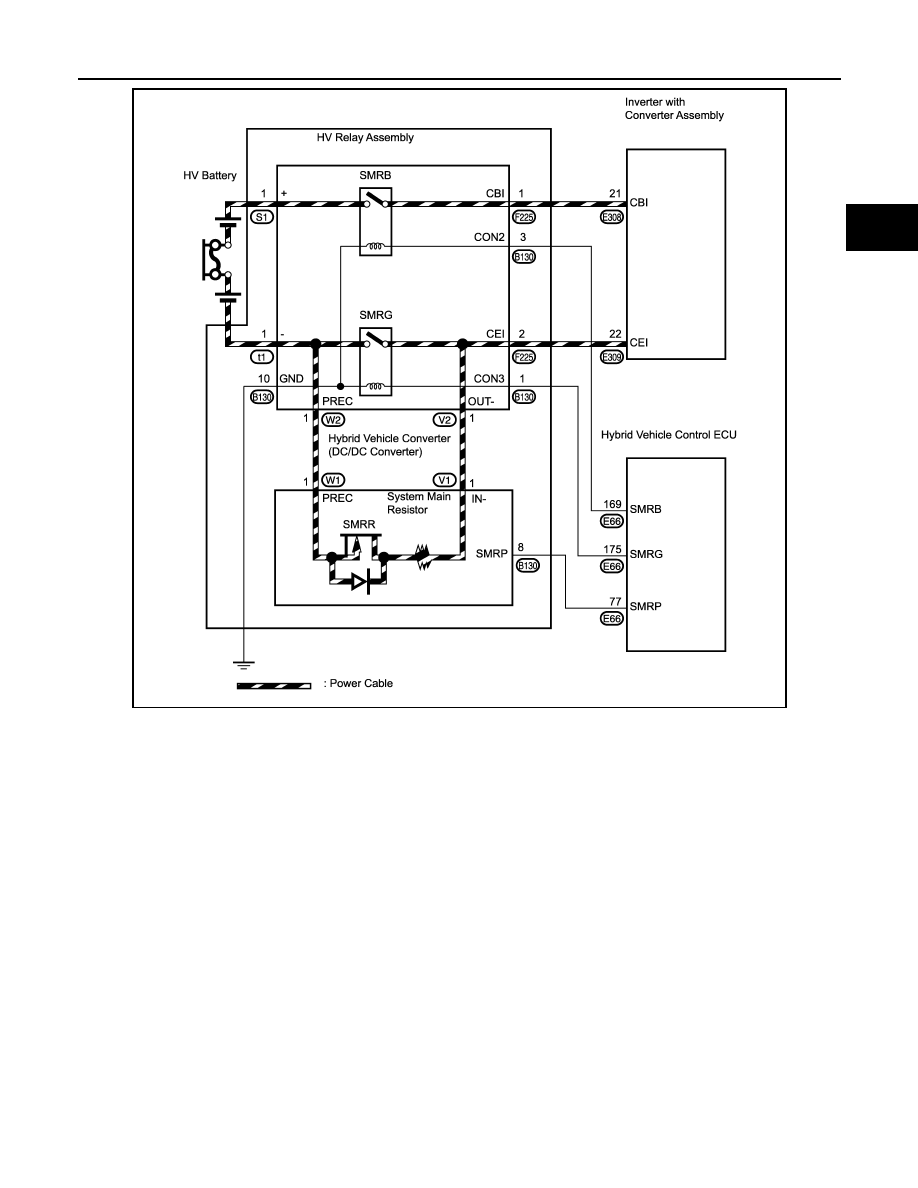
JMCIA0124GB
|
|
|
P0ADB-227, P0ADC-226 HBC-437 < COMPONENT DIAGNOSIS > D E F G H I J K L M A B HBC N O P JMCIA0124GB |