Nissan Altima HL32 Hybrid. Manual - part 670


  Index      Nissan     Nissan Altima HL32 Hybrid (2009 year) - Service and Repair Manual


Search            


Content   ..  668  669  670  671   ..


Nissan Altima HL32 Hybrid. Manual - part 670


P0AA6-526, P0AA6-611, P0AA6-612, P0AA6-613, P0AA6-614

HBC-429

< COMPONENT DIAGNOSIS >

D

E

F

G

H

I

J

K

L

M

A

B

HBC

N

O

P

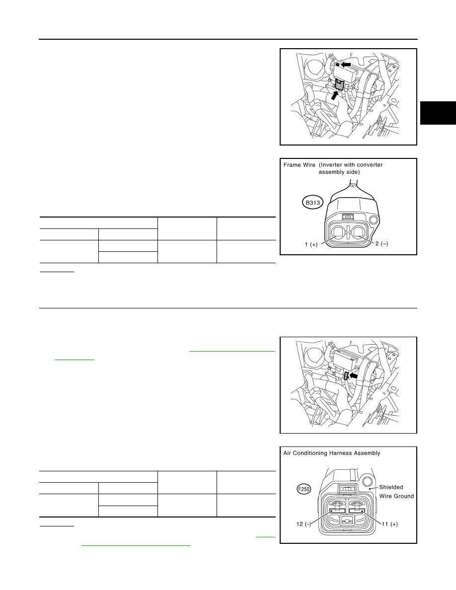
3. Disconnect the frame wire from the inverter with converter

assembly.

4. Using a megohmmeter set to 500 V, measure the resistance

according to the value(s) in the table below.

NOTE:

• Be sure to set the megohmmeter to 500 V when perform-

ing this test. Using a setting higher than 500 V can result

in damage to the component being inspected.

OK or NG

OK

>> GO TO 14.

NG

>> GO TO 16.

14.

CHECK AIR CONDITIONING HARNESS ASSEMBLY

CAUTION:

Be sure to wear insulated gloves.

1. Check that the service plug grip is not installed.

2. Disconnect the air conditioning harness assembly from the

inverter with converter assembly (See 

HBC-638, "Removal and

Installation"

).

3. Using a megohmmeter set to 500 V, measure the resistance

according to the value(s) in the table below.

OK or NG

OK

>> Replace inverter with converter assembly (See 

HBC-

638, "Removal and Installation"

)

NG

>> GO TO 15.

AWCIA0027ZZ

HV Relay Assembly

Ground

Resistance

Harness connector

Terminal

E313

1 (High voltage +)

Ground

10 M

Ω or higher

2 (High voltage 

−)

JMCIA0195GB

ALCIA0104ZZ

Air Conditioning Harness Assembly

Ground

Resistance

Harness connector

Terminal

F250

12 (

−)

Ground

3 M

Ω or higher

11 (+)

JMCIA0200GB

HBC-430

< COMPONENT DIAGNOSIS >

P0AA6-526, P0AA6-611, P0AA6-612, P0AA6-613, P0AA6-614

15.

CHECK AIR CONDITIONING HARNESS ASSEMBLY

CAUTION:

Be sure to wear insulated gloves.

1. Check that the service plug grip is not installed.

2. Disconnect the air conditioning harness assembly from the elec-

tric compressor.

-

Green lock (1)

3. Using a megohmmeter set to 500 V, measure the resistance

according to the value(s) in the table below.

NOTE:

• Be sure to set the megohmmeter to 500 V when perform-

ing this test. Using a setting higher than 500 V can result

in damage to the component being inspected.

OK or NG

OK

>> Go to air conditioning system.

NG

>> Replace air conditioning harness assembly.

16.

CHECK FRAME WIRE

CAUTION:

Be sure to wear insulated gloves.

1. Check that the service plug grip is not installed.

2. Disconnect the frame wire from the HV relay assembly (See 

HBB-105, "Removal and Installation"

).

3. Using a megohmmeter set to 500 V, measure the resistance

according to the value(s) in the table below.

NOTE:

• Be sure to set the megohmmeter to 500 V when perform-

ing this test. Using a setting higher than 500 V can result

in damage to the component being inspected.

ALCIA0109ZZ

Air Conditioning Harness Assembly

Ground

Resistance

Harness connector

Terminal

F250

12 (

−)

Ground

10 M

Ω or higher

11 (+)

Air Conditioning Harness Assembly

Ground

Resistance

Harness connector

Terminal

F250

12 (

−)

Shielded wire 

ground

10M

Ω or higher

11 (+)

JMCIA0200GB

Frame Wire (HV Relay Side)

Ground

Resistance

Harness connector

Terminal

E308

1 (+)

Ground

10 M

Ω or higher

E309

1 (

−)

JMCIA0195GB

P0AA6-526, P0AA6-611, P0AA6-612, P0AA6-613, P0AA6-614

HBC-431

< COMPONENT DIAGNOSIS >

D

E

F

G

H

I

J

K

L

M

A

B

HBC

N

O

P

OK or NG

OK

>> GO TO 17.

NG

>> Replace frame wire.

17.

CHECK HYBRID VEHICLE CONVERTER

CAUTION:

Be sure to wear insulated gloves.

1. Check that the service plug grip is not installed.

2. Disconnect the w1, v1 and v3 hybrid vehicle converter (DC/DC

converter) connectors from the HV relay assembly (See 

HBB-

105, "Removal and Installation"

). Using a megohmmeter set to

500 V, measure the resistance according to the value(s) in the

table below.

NOTE:

• Be sure to set the megohmmeter to 500 V when perform-

ing this test. Using a setting higher than 500 V can result

in damage to the component being inspected.

3. Connect the hybrid vehicle converter (DC/DC converter) connectors.
OK or NG

OK

>> Replace HV relay assembly (See 

HBB-105, "Removal and Installation"

)

NG

>> Replace hybrid vehicle converter (See 

HBB-103, "Removal and Installation"

).

18.

CHECK HYBRID TRANSAXLE AREA

CAUTION:

Be sure to wear insulated gloves.

1. Check that the service plug grip is not installed.

2. Remove the compressor fuse cover from the inverter with con-

verter assembly (See 

HBC-638, "Removal and Installation"

).

3. Disconnect the generator cable and motor cable from the

inverter with converter assembly.

Frame Wire (HV Relay Side)

Ground

Resistance

Harness connector

Terminal

E308

1 (+)

Shielded wire 

ground

10M

Ω or higher

E309

1 (

−)

Frame Wire (HV Relay Side)

Ground

Resistance

Harness connector

Terminal

w1

1 (High voltage 

precharge)

Ground

10 M

Ω or higher

v3

1 (High voltage +)

v1

1 (High voltage 

−)

JMCIA0156GB

ALCIA0103ZZ

HBC-432

< COMPONENT DIAGNOSIS >

P0AA6-526, P0AA6-611, P0AA6-612, P0AA6-613, P0AA6-614

4. Using a megohmmeter set to 500 V, measure the resistance

according to the value(s) in the table below.

NOTE:

• Be sure to set the megohmmeter to 500 V when perform-

ing this test. Using a setting higher than 500 V can result

in damage to the component being inspected.

-

A/C fuse (1)

OK or NG

OK

>> Replace hybrid transaxle (See 

TM-36, "Removal and

Installation"

).

NG

>> Replace inverter with converter assembly (See 

HBC-

638, "Removal and Installation"

).

Inverter with converter assembly

Ground

Resistance

Component connector

Terminal

Compressor fuse

Ground

1.0 M

Ω or higher

ALCIA0108ZZ


Content   ..  668  669  670  671   ..